Die casting leak testing answers a practical question: will a housing, cover, or fluid-handling component contain its specified medium at the required pressure? A casting can look sound on the outside and still contain an interconnected pore, a crack, or a cold shut that opens a path through the wall. A good test therefore needs more than a sensitive instrument. It needs the right acceptance limit, a repeatable sealing fixture, controlled temperature, and a measurement method suited to the part’s volume and production rate.
This guide explains three air-based methods used for die-cast components: pressure decay, differential pressure, and flow measurement. It also shows how to interpret a result, set up a repeatable production test, and trace a failed part back to either the fixture or the casting process.
What Does a Die Casting Leak Test Actually Measure?
An integral leak test evaluates the complete sealed assembly or cavity. It reports whether gas escapes faster than an agreed limit under specified conditions; it does not automatically identify the location of the leak. The word leak-tight is always relative to a defined test pressure, medium, temperature, measurement time, and allowable leakage rate. It does not mean that the part has a mathematically zero leak rate.
For a die casting, the test boundary may include the metal wall, machined ports, threaded holes, gaskets, plugs, and the test fixture itself. If a production test fails, the signal could come from any of these elements. A well-designed process separates fixture faults from casting defects before changing the die or shot settings.
Where Can Leakage Start in a Die-Cast Part?
Common paths include interconnected gas or shrinkage porosity, thin-wall pinholes, through-wall cracks, and cold shuts. Machining can expose subsurface porosity that was covered by the as-cast skin. A porous region is not necessarily a leak: it becomes a functional leak when a continuous path connects the pressurized cavity to the outside or to another cavity. Our guide to internal aluminum die casting defects explains these mechanisms in more detail.
The location matters. Leakage concentrated near a thick section may point toward shrinkage porosity or a thermal hot spot. Leakage at a flow-front meeting point can suggest a cold shut or trapped gas. A failure that appears only after machining may call for a review of machining allowance, wall thickness, and the location of internal pores. These are diagnostic clues, not proof by themselves; sectioning, imaging, and process records should confirm the cause.
Define the Pass/Fail Requirement Before Choosing a Tester
Start with the component’s service duty. A coolant housing, gearbox housing, valve body, and sealed electronics enclosure may have very different consequences of leakage. The customer drawing or validation plan should define, or allow the team to agree on:
- Which cavity and interfaces are tested, including whether the test is on the bare casting or the finished assembly.
- Test medium and pressure, including whether pressure is stated as gauge or absolute pressure.
- Maximum acceptable leak rate and its units, such as mL/min of air at a stated reference condition.
- Fill, stabilization, measurement, and vent times.
- Test temperature range, part condition, and the point in the production sequence at which the test occurs.
- Required evidence: a pass/fail record, numeric leak rate, traceability, or leak-location investigation.
There is no universal air leak limit for all die castings. A limit that works for one part cannot be copied to another without considering service conditions, cavity volume, test pressure, and the risk of failure. An air-test result also should not be treated as a direct prediction of water, oil, or refrigerant leakage without an application-specific correlation.
How Do the Three Main Die Casting Leak Testing Methods Work?
All three methods begin with a sound test boundary and a controlled pressure. They differ in what the instrument senses: a pressure drop in the test volume, a pressure difference against a reference, or gas flow required to replace escaping air. The basic sequence for pressure-based testing is fill → stabilize → measure → vent. Stabilization is essential because recently compressed air changes temperature and pressure even when the part has no leak. Equipment makers Uson and INFICON describe this sequence in their testing guides.
1. Pressure Decay Leak Testing
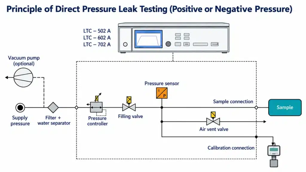
Pressure decay testing fills the part with air, isolates it from the supply, waits for the system to stabilize, and monitors the pressure during a defined interval. A falling pressure can indicate a leak. This is a common choice for production testing because the circuit is comparatively simple and the result can be recorded automatically.
The test measures the whole pressurized volume, not just the casting cavity. Tubing, valves, fittings, and any empty space in the fixture add to the volume. For the same actual leak, a larger volume gives a smaller pressure drop over a fixed time. An engineer may therefore need a longer measurement window, a more sensitive sensor, or a smaller test volume when a large housing must meet a tight limit.
How Is Pressure Drop Converted to Leak Rate?
For a rigid volume at approximately constant temperature, an illustrative conversion is:
Qref ≈ (Vtest × Δp / pref) × (60 / t)
Here Qref is an approximate volume leak rate in mL/min at the stated reference pressure, Vtest is the total test volume in mL, Δp is the pressure fall in the measurement window, pref is the reference absolute pressure in the same pressure units, and t is the measurement time in seconds. Gauge-pressure changes and absolute-pressure changes have the same numerical size, but the reference pressure in the denominator must be absolute. The conversion assumes a stable gas temperature, a nearly fixed volume, and a small pressure change relative to the test pressure. Real instruments may apply their own calibration and compensation.
For example, if the total test volume is 1,000 mL and pressure falls by 1 mbar over 30 seconds, using 1,013 mbar as the reference pressure gives approximately 2.0 mL/min. This is a calculation example, not a recommended acceptance limit. The instrument manufacturer’s explanation of pressure decay and leak rate also stresses that total circuit volume must be included.
Pressure decay works well when the part can be sealed consistently and the expected leak creates a measurable signal within the available cycle time. It becomes harder when a large cavity is paired with a very low allowable leak rate, or when temperature drift, fixture flex, and seal movement are large relative to the expected pressure change.
2. Differential Pressure Leak Testing
Differential pressure testing fills the part and a reference side to the same pressure. After stabilization, a differential sensor tracks the pressure difference between them. Because the sensor measures a small difference rather than the entire test pressure, this arrangement can offer better resolution for small leaks in suitable applications. Uson’s method description explains the fill, equalization, measurement, and vent stages.
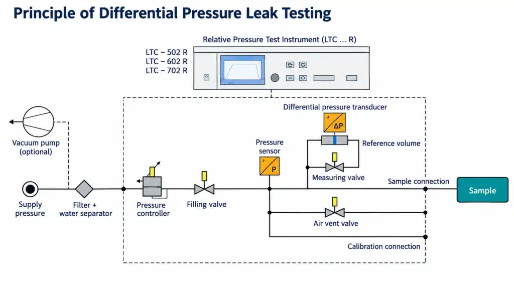
The reference may be a calibrated volume or a known-good master part, depending on the instrument and fixture design. Matching the two sides can help reduce common disturbances. It does not automatically cancel every temperature effect: if the reference and production part differ in volume, thermal mass, location, or pressurized expansion, they can drift differently. The reference side must also be leak-tight and checked routinely.
When Does a Reference Part Help?
A reference part is useful when its behavior closely follows the production part, especially for large or somewhat compliant test volumes. It can be less helpful if the master is held at a different temperature or its seals age differently. The fixture designer should compare both sides under normal production conditions rather than assume that adding a reference always improves the result. Uson’s guidance on reference volumes gives practical examples of these trade-offs.
Differential pressure is a candidate when the reject limit is too small for a robust direct pressure-decay measurement within the required cycle. A trial on real parts, with known leak standards and repeated loading, is still needed to prove that the system can separate passing and failing components.
3. Flow-Based Leak Testing
A flow-based leak test can be arranged in two ways. In the first, a high-precision mass-flow sensor is connected directly to the die casting’s test circuit. The part is filled with compressed air and allowed to stabilize. The sensor then measures the air flow associated with leakage, and the instrument displays the leak rate directly. Unlike pressure decay or differential pressure testing, this arrangement does not require the operator to enter the part’s test volume to convert a pressure change into a flow-rate result.
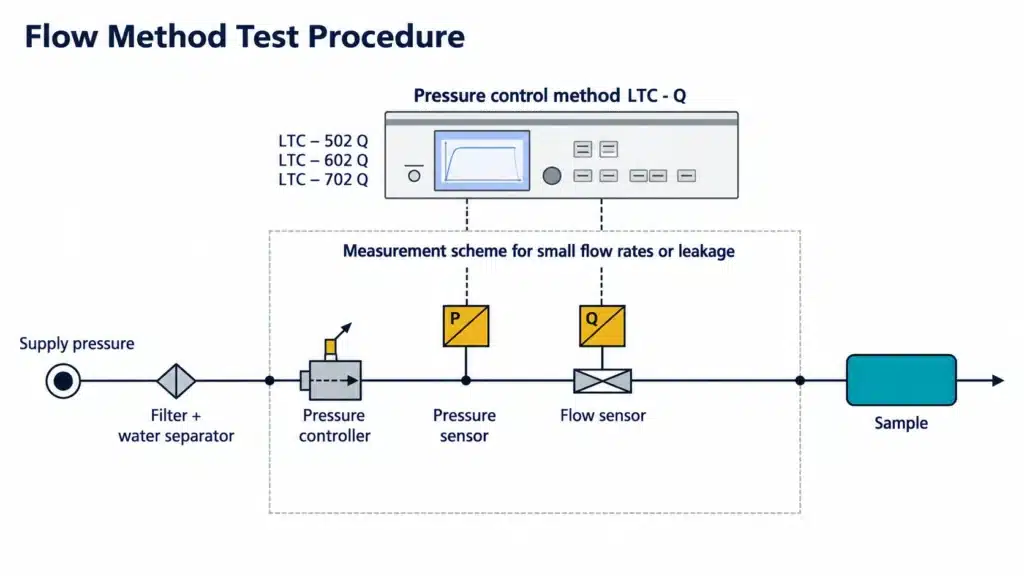
The second arrangement is intended for castings with a relatively large internal volume and a small allowable leak rate. A mass-flow sensor connects the test part to a reference volume. Both sides are filled with compressed air and given time to stabilize. The filling valve and the valve that bypasses the sensor are then closed, leaving the sensor as the flow path between the two sides. If the part has a small leak, air moves from the reference volume through the sensor toward the part. The measured transfer flow is recorded as the leak-test result.

Why Do Flow Results Still Need Stabilization?
Air can move because a leak exists, but also because a part or fixture is warming, cooling, or deforming. A flow signal observed immediately after filling may reflect settling rather than leakage. For that reason, flow methods still require a defined stabilization stage, sound seals, a calibrated sensor, and a test window. Flow testing does not remove the need to control test pressure and temperature.
| Method | Primary signal | Typical reason to consider it | Main setup risk |
|---|---|---|---|
| Pressure decay | Pressure fall in the isolated test volume | Straightforward integral test on a stable, sealable part | Large volume or thermal drift hides a small leak |
| Differential pressure | Difference between test and reference sides | Greater resolution is needed for a small pressure change | Reference and part respond differently to temperature or fixture movement |
| Flow-based | Make-up or transfer flow at controlled pressure | A flow-rate result is needed, or a large volume makes decay slow | Residual filling, drift, or fixture leakage is mistaken for part leakage |
No single method is automatically best for every casting. The selection should be demonstrated against the actual reject limit, total test volume, part temperature range, fixture, and target cycle time.
How to Build a Repeatable Test for a Die-Cast Housing
The tester only measures what the fixture presents to it. For a complex housing, the fixture often determines whether the production result is trustworthy. A useful setup review covers cavity isolation, sealing surfaces, trapped test volume, temperature, and test-system verification.
Design the Fixture Around the Test Boundary
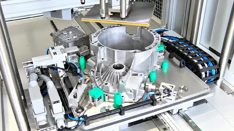
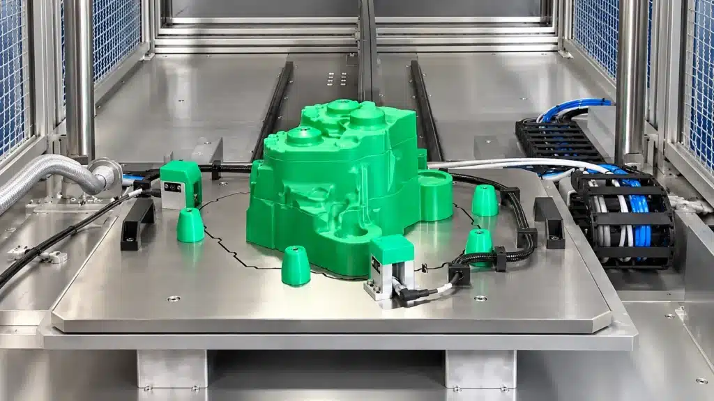
Map every port and passage on the drawing. Decide which openings will be supplied, plugged, or isolated, and check that no hidden passage bypasses the intended test. Use sealing lands that are flat, accessible, and repeatable after machining. A rough as-cast face may require a different seal or a prepared surface. Avoid fixture loads that bend a thin wall or temporarily close a genuine leak path.
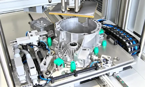
For a large housing, a rigid insert or volume-displacement feature can reduce the amount of air that must be filled. The insert must not deform under test pressure, damage the part, block a leakage path, or create an unstable seal. Its size and position are part of the validated fixture design. Uson also notes that reducing test volume can improve the response and cycle time of pressure-decay systems in suitable applications.
Control the Full Test Sequence
- Load and seal: Confirm that the part is seated, clamps are in position, and the correct fixture recipe is selected.
- Fill: Reach the specified pressure without an excessive transient. A gross-leak check can reject parts that cannot hold enough pressure to enter the fine-leak measurement.
- Stabilize: Allow compressed air, the casting, and seals to settle. Establish the time from trials across the normal temperature range, not from a single ideal sample.
- Measure: Record pressure change or flow for the specified interval and compare it with the approved limit.
- Vent and unload: Release stored pressure before removing the part. Save the result with the relevant part and fixture identifiers if traceability is required.
Hot parts straight from machining or washing may produce a different result from cooled parts. Drafts, direct sunlight, a warm hand on a small part, and compressor pressure fluctuations can also disturb a sensitive test. A repeatable test keeps the part condition and environment within a defined window. A mathematical temperature correction may help in some systems, but it is not a substitute for stable handling and adequate stabilization.
Verify the Measurement System, Not Just the Sensor
Before production release, challenge the complete setup with a known-good part, a known-leak standard or calibrated leak, and deliberately mis-seated seals. Repeat the checks after fixture maintenance and at a frequency defined by the quality plan. Confirm that the test discriminates around the reject threshold with the normal variation in operators, part temperature, and loading position.
The test record should state the pressure, limit, units, cycle times, calibration status, fixture version, and part state. If a numerical leak rate is reported, document the reference conditions used for that rate. If the test is conducted on a bare casting but the product seals only after assembly, keep those two validation questions separate.
Example: Planning a Test for a Transmission Housing
Consider a large die-cast transmission housing with several machined ports. The team needs to check the casting boundary before assembly. A possible engineering trial could use 2 bar gauge air pressure, a 30-second measurement window, and a 2 mL/min air leak limit. These numbers are only an illustration from the supplied technical reference; they are not a general specification for transmission housings or a statement of CASTMOLD’s standard capability. The product owner must approve actual values from the service requirement and validation plan.
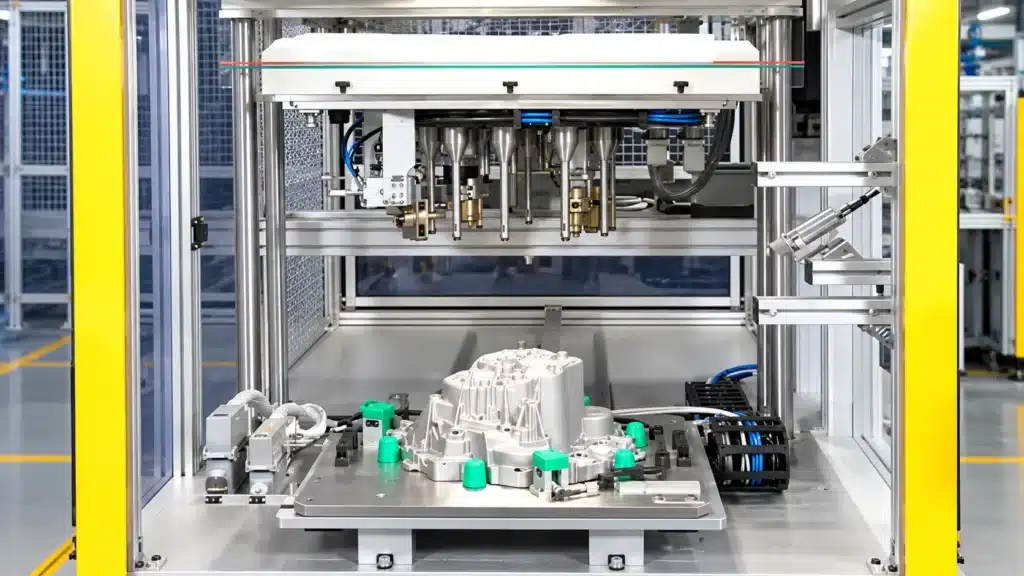
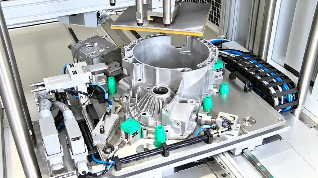
The engineer first identifies all ports and tests whether the fixture seals each one consistently. Because the housing is large, the fixture may use a rigid insert to reduce test volume. The team then runs a set of known-good and known-leak parts at different starting temperatures and measures how much stabilization time is needed. If pressure decay cannot clearly separate parts around the 2 mL/min trial limit within the available cycle, differential pressure or flow-based testing can be evaluated on the same parts. Changing methods does not change the product’s acceptance requirement; it changes how the requirement is measured.
If a part fails, a second step locates the path. Local methods, such as applying a suitable bubble solution or using another validated localization technique, can point to a port seal, machined surface, crack, or porous wall. Any wet localization method must be compatible with the part and cleaned afterward when required. The integral test confirms a leakage rate; the localization step helps determine what to fix.
What Should You Do When a Casting Fails?
Do not assume every red result means the die is defective. Work from the easiest reversible checks to the material investigation:
- Retest the fixture: Inspect O-rings, plugs, clamps, hoses, valves, and the part’s seating. Compare with a known-good master. A fixture leak can mimic a porous casting.
- Check the part condition: Look for chips on a sealing land, residual coolant in a passage, a blocked port, or a part that is outside the allowed temperature range.
- Locate the escape path: Use a validated localization method, then mark the location and record whether it is near a machined feature, thick section, or flow-front meeting point.
- Identify the material mechanism: Use suitable inspection or a controlled section of representative rejects to distinguish interconnected gas porosity, shrinkage porosity, cracks, and cold shuts.
- Correct the root cause: Depending on the evidence, review wall transitions, machining allowance, gate and overflow positions, venting, shot profile, and die thermal balance. Our HPDC process guide provides context for those controls.
- Revalidate: Test parts after the change, confirm the defect rate and measurement repeatability, and retain the records needed for customer approval.
Vacuum impregnation or another sealing treatment may be possible for certain parts, but it should follow the customer’s specification and validation requirements. It should not replace investigation of a recurring casting defect or be assumed suitable for every safety-critical or pressure-bearing application.
Die Casting Leak Testing: Frequently Asked Questions
Is a pressure test the same as a leak test?
No. A proof or burst test checks whether a component withstands a specified load. A leak test checks how much medium escapes under defined conditions. One procedure may include both objectives, but each needs its own pressure, hold time, acceptance criteria, and safety controls.
Can a casting pass an X-ray inspection and still leak?
Yes. Imaging can reveal internal indications, but functional leakage depends on whether a connected path reaches the surface under the test conditions. A leak test evaluates the sealed boundary directly. Imaging and sectioning are useful follow-up tools for diagnosing why a part failed.
Does a higher air-test pressure always make the test better?
No. Pressure must represent the approved test requirement and the component’s safe test range. Raising it can change seal behavior, part deformation, and leakage through a defect. A result at one pressure should not be extrapolated to a different pressure without validation.
Which method is best for a large housing?
There is no universal choice. Begin with the allowable leak rate, pressure, total test volume, temperature variation, and cycle-time target. Try pressure decay with a stable low-volume fixture; then compare differential pressure or flow measurement if the pressure change cannot be resolved reliably. Demonstrate the choice with reference leaks and real production parts.
Plan the Test with the Casting Process
Die casting leak testing works best when the part design, casting process, machining plan, fixture, and acceptance limit are developed together. A reliable result tells the team whether the finished boundary meets its specified leakage requirement; a disciplined failure investigation tells them what to improve.
If you are developing a pressure-tight aluminum or zinc die-cast component, contact CASTMOLD with the drawing, 3D model, alloy, test medium, pressure, allowable leak rate, and annual volume. Those inputs let the engineering team review manufacturability and propose a test approach that can be validated for your application.
Aluminum Die Casting Services
Learn more about our aluminum high pressure die casting services in China.