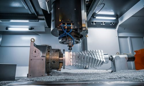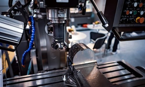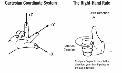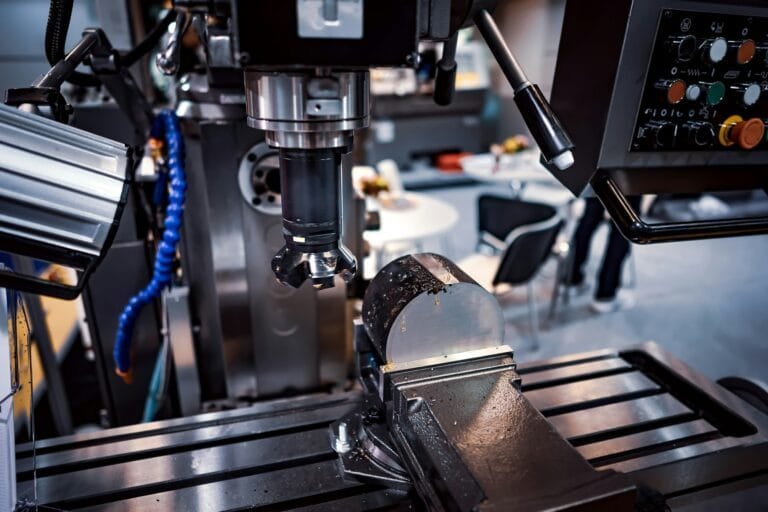
CNC machine systems determine how a machine reads an NC program, drives each axis, checks its actual position, and controls tool changes, coolant, and other auxiliary functions. When you press the green “CYCLE START” button, these five systems begin working together within milliseconds.
In the previous two articles, we introduced the historical development of CNC machine tools and explained CNC coordinate systems.
In this article, we will go one step further:
What systems make up a CNC machine tool? How do these systems work together? What exactly happens inside the machine you operate every day?
What Happens When CNC Machine Systems Receive a CYCLE START Command?
When you press the green CYCLE START button on the control panel, the machine begins moving according to the CNC program.
The entire process may look almost magical.
However, behind this seemingly simple action is a highly coordinated and precise system:
One component reads the machining program.
Another converts the commands into electrical signals.
Another drives the motors.
Another continuously checks the actual machine position.
Another controls coolant, tool changes, and other auxiliary operations.
These components make up the five core systems of a CNC machine tool.
Understanding these five systems is not just about satisfying curiosity.
When a machine fault occurs, this knowledge can help you determine which part of the system may be causing the problem. As you continue learning more advanced CNC technology, these five systems will also provide a clear framework for understanding new concepts.
System 1: CNC Controller — The “Brain” of the Machine
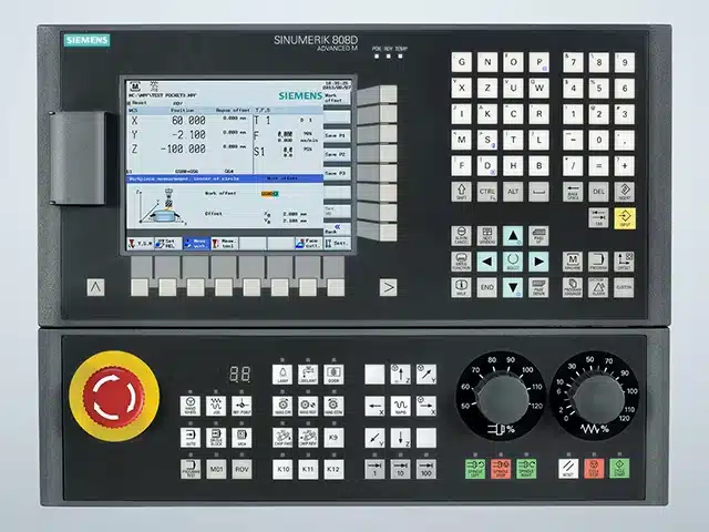
The CNC controller is the core of the entire machine tool. It is what we commonly call the CNC system, numerical control unit, or CNC control system.
Its operating process can be explained through five main steps.
Reading the Program
The CNC controller reads the NC program from internal memory, a CF card, a USB device, or a network interface.
Decoding
It translates G-code, M-code, and other program instructions into data that the internal control system can process.
Interpolation Calculation
According to the programmed motion commands, the CNC controller calculates how far each axis must move during every time interval.
This is one of the most important calculations performed by the CNC system.
For example, a command to move from Point A to Point B must be divided into countless extremely small movement steps. The controller calculates and coordinates these steps in real time.
Sending Control Commands
The calculated movement amount for each axis is converted into electrical control signals and sent to the servo system.
Coordinating Auxiliary Functions
The CNC controller also coordinates M-code functions such as:
- Spindle speed control
- Automatic tool changing
- Coolant control
- Machine clamping and releasing
- Other auxiliary machine operations
The CNC controller does not simply execute the program passively.
It also continuously receives position feedback from each machine axis and corrects movement errors in real time.
The control panel and display screen that operators use every day are the human-machine interface of the CNC controller.
Through this interface, operators can enter programs, modify parameters, check coordinates, monitor machining status, and communicate with the CNC system.
System 2: Servo System — The “Muscles” of the Machine
The CNC controller may issue a command such as:
Move the X-axis by 0.001 mm.
However, this digital command must be converted into actual mechanical movement. This is the job of the servo system.
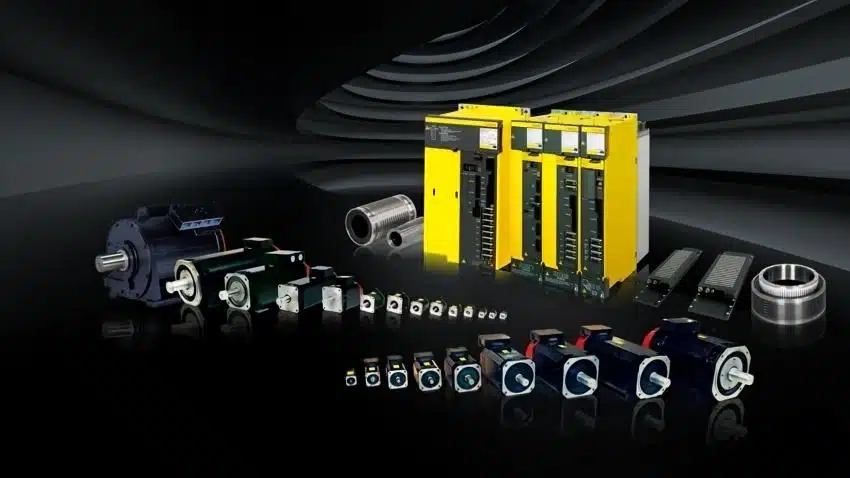
A servo system mainly consists of two parts.
Servo Drive
The servo drive receives control signals from the CNC controller, amplifies them, and converts them into electrical power that can drive the motor.
It works like a highly precise power amplifier.
Servo Motor
The servo motor converts electrical energy into mechanical rotational movement.
The main difference between a servo motor and a conventional motor is that a servo motor is equipped with a position encoder.
This allows it to control the rotational angle accurately and respond extremely quickly. A servo motor can start, stop, accelerate, decelerate, or change direction within milliseconds.
A CNC machine tool normally contains several servo systems.
Feed-Axis Servo Systems
The X-axis, Y-axis, and Z-axis normally each have an independent feed servo system.
These servo systems control the movement of the cutting tool, spindle head, and worktable.
Spindle Servo System
The spindle servo controls the rotational speed of the spindle and cutting tool.
The focus of the spindle servo is slightly different from that of the feed-axis servo.
Feed-axis servo systems mainly focus on positioning accuracy. The commanded movement distance must be achieved accurately.
The spindle servo mainly focuses on speed stability. During cutting, the spindle speed must remain stable and should not fluctuate significantly because of changing cutting forces.
For a five-axis CNC machine, two additional servo systems are normally required to control the rotary axes, such as the A-axis, B-axis, or C-axis.
As a result, five or six servo systems may be operating simultaneously during five-axis machining.
System 3: Mechanical Structure — The Skeleton and Joints
The servo motor generates rotational motion.
However, CNC machining requires precise linear movement, rotational positioning, and controlled movement of the cutting tool and workpiece.
The machine’s mechanical structure converts motor rotation into accurate movement of the machine components.
The main parts of the mechanical structure include the following.
Machine Bed and Frame
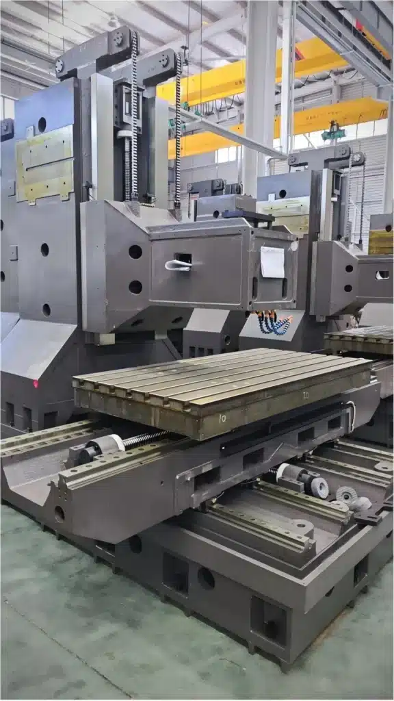
The machine bed is the basic supporting structure of the CNC machine tool.
It is normally made from cast iron or welded steel plates.
A high-quality machine bed must provide:
- High structural rigidity
- Good vibration resistance
- Stable dimensional performance
- Reliable support for moving components
The rigidity and vibration resistance of the machine bed are essential for maintaining machining accuracy.
Linear Guideways
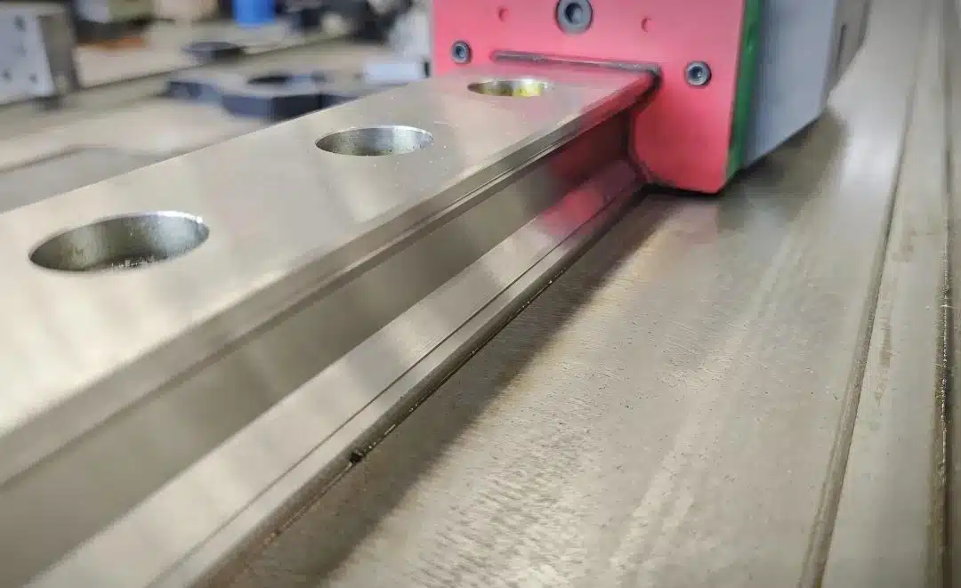
Linear guideways guide the worktable and spindle head along specific movement directions.
Modern machining centers commonly use linear rolling guideways because they provide:
- Low friction
- High movement accuracy
- Fast response
- High feed speeds
- Good positioning repeatability
High-precision CNC machines may use hydrostatic guideways. These guideways operate with an extremely low level of friction and offer excellent smoothness and precision.
Ball Screw
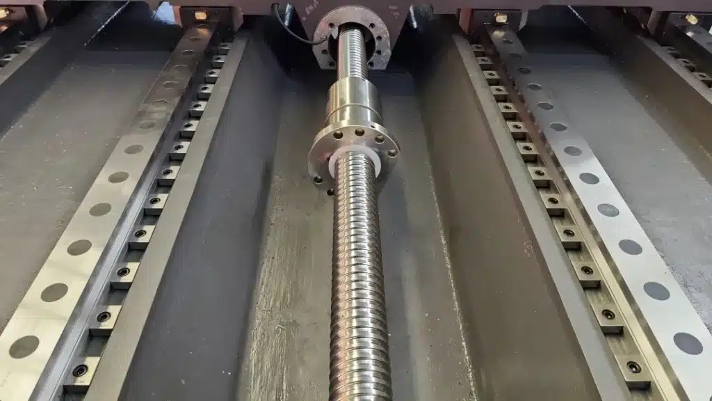
The ball screw is a critical component that converts the rotational movement of the servo motor into the linear movement of the worktable or spindle head.
Inside the ball screw assembly, steel balls roll between the screw shaft and nut to transmit force.
Because rolling friction is much lower than sliding friction, ball screws can provide highly efficient transmission and micrometer-level positioning accuracy.
Spindle
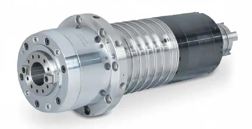
The spindle holds the cutting tool and rotates it at high speed.
Spindle accuracy, especially spindle runout, directly affects the final machining accuracy and surface quality.
The maximum spindle speed also determines the cutting speeds that the machine can support.
High-speed CNC spindles can reach 40,000 rpm or even higher.
System 4: Measurement and Feedback System — The “Eyes” of Closed-Loop Control
The feedback system is extremely important, although many CNC beginners may not fully understand its function.
Suppose the CNC controller commands the servo motor to rotate ten revolutions.
How does the control system know whether the motor actually completed exactly ten revolutions?
How does it know whether the cutting tool moved the required distance?
The answer is the measurement and feedback system.
Its function is to measure the actual machine position in real time and send the information back to the CNC controller.
The controller compares the actual position with the commanded position and automatically corrects any deviation.
This continuous process can be described as:
Command → Execution → Actual Position Measurement → Error Comparison → Command Correction
This cycle is called closed-loop control, and it is one of the core mechanisms that allows CNC machines to achieve high positioning accuracy.
Two common types of position measurement devices are used in CNC machines.
Rotary Encoder
A rotary encoder is normally installed on the servo motor shaft.
It measures the rotational angle and speed of the motor.
However, because the rotary encoder measures the position at the motor side rather than directly at the worktable, errors caused by the ball screw, coupling, thermal expansion, or elastic deformation may still exist.
This configuration is known as a semi-closed-loop control system.
Most machining centers use this type of feedback system.
According to the original article, the typical positioning accuracy is approximately:
±0.005 to ±0.01 mm
Linear Scale
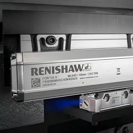
A linear scale is installed directly beside the machine guideway and measures the actual linear displacement of the worktable.
Because it directly measures the worktable position, it can compensate for errors generated by the ball screw and other transmission components.
This configuration is known as a fully closed-loop control system.
It provides higher positioning accuracy and may achieve approximately:
±0.001 mm
High-precision CNC machines and precision five-axis machining centers are commonly equipped with linear scales.
System 5: Auxiliary Function System — Helping the Machine Complete the Work
The first four systems ensure that the cutting tool can move accurately.
However, precise movement alone is not enough to complete an entire machining process.
A CNC machine also requires several auxiliary systems.
Automatic Tool Changer
The Automatic Tool Changer, commonly abbreviated as ATC, is one of the most important features of a machining center.
The tool magazine stores multiple cutting tools. When a tool change is required, the tool-changing mechanism or robotic arm automatically completes the operation.
A complete tool change usually takes only a few seconds.
Tool magazine capacities may range from approximately eight tools to more than one hundred tools, depending on the machine configuration.

Cooling System
During machining, a large amount of heat is generated between the cutting tool and the workpiece.
Cutting fluid or coolant performs several functions:
- Reducing the cutting temperature
- Lubricating the cutting zone
- Flushing away chips
- Protecting the cutting tool
- Improving surface quality
Common cooling methods include external coolant spraying and through-spindle coolant.
Through-spindle coolant flows through internal passages in the spindle and cutting tool and is delivered directly to the cutting area.
Pneumatic and Hydraulic Systems
Pneumatic and hydraulic systems are used for machine operations that require relatively high force.
Typical applications include:
- Workpiece clamping
- Tool-changing movements
- Tool unclamping
- Spindle tool release
- Fixture operation
- Hydraulic positioning mechanisms
PLC — Programmable Logic Controller
The CNC controller mainly handles motion control.
However, a machine tool also contains a large number of switching and sequence-control operations, such as:
- Automatic tool changing
- Coolant switching
- Protective-door interlocking
- Hydraulic clamping
- Lubrication control
- Alarm detection
- Machine safety functions
These operations are normally handled by an integrated Programmable Logic Controller, or PLC.
The PLC and CNC controller work together to form the complete machine control system.
Signal Flow Between the Five Core Systems
The entire CNC machining process can be understood through the following signal chain:
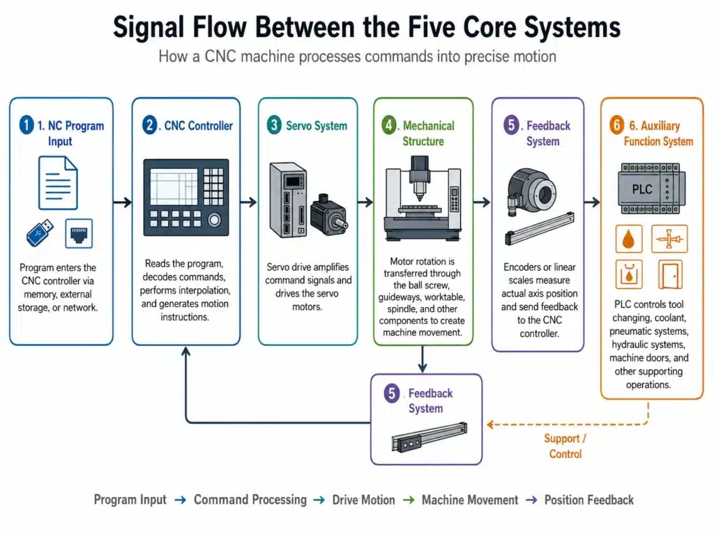
This is what happens after the operator presses the CYCLE START button.
It is a highly precise closed-loop control process that may repeat thousands of times every second.
Introduction to Mainstream CNC Control System Brands
After understanding the role of the CNC controller, we can take a brief look at several major CNC control system brands.
FANUC
FANUC is a Japanese brand and one of the most widely used CNC control system manufacturers in the world.
Its systems are known for stability, reliability, and a well-established technical ecosystem.
FANUC systems are widely used in manufacturing plants and are often considered a suitable starting point for CNC operators and programmers.
Siemens SINUMERIK
Siemens is a German brand, and its SINUMERIK CNC systems are widely used on European machine tools.
SINUMERIK ONE is commonly installed on high-end machine tools and provides powerful functions and comprehensive support for five-axis machining.
However, compared with some other systems, its learning curve may be relatively steep.
Siemens CNC systems are widely used in automotive, aerospace, and advanced manufacturing applications.
Heidenhain TNC
Heidenhain is also a German brand.
Its TNC control systems mainly focus on milling machines and machining centers.
Heidenhain systems are well known for their advanced five-axis functions and are highly regarded in aerospace machining, precision mold manufacturing, and other high-accuracy applications.
Representative Chinese CNC Control System Brands
Chinese CNC control system brands have developed rapidly in recent years.
| Brand | Company | Main Advantages | Market Positioning | Five-Axis Support |
|---|---|---|---|---|
| Huazhong 9 Series | Huazhong CNC | Chinese-developed CPU and independently controlled technology | Entry- to mid-level systems and domestic substitution | Moderate |
| GSK | Guangzhou CNC | Competitive pricing and a complete supporting product range | Economical CNC machines | Moderate |
| Kede GNC62 | Kede CNC | Five-axis simultaneous machining and turn-mill functions | Mid- to high-end market | Relatively strong |
| SYNTEC | Syntec Technology | Strong CAM compatibility, user-friendly interface, and widespread use on Chinese five-axis machines | Mid-range market with rapid five-axis growth | Relatively strong |
Summary: Understanding CNC Machine Systems
A CNC machine tool consists of five core systems.
CNC controller:
The brain of the machine. It reads the program, performs interpolation calculations, and sends movement commands.
Servo system:
The muscles of the machine. It drives the motors and controls the precise movement of each axis.
Mechanical structure:
The skeleton and joints of the machine, including the machine bed, guideways, ball screws, worktable, and spindle.
Measurement and feedback system:
The eyes of the machine. It measures the actual position and enables closed-loop control.
Auxiliary function system:
The hands of the machine. It controls tool changing, coolant, hydraulic systems, pneumatic systems, and other supporting functions.
When these five systems work together, a CNC machine can convert a digital machining program into accurate, repeatable, and automated manufacturing operations.
CNC Machining Support from Cast Mold
At Cast Mold, CNC machining is an important part of our one-stop manufacturing service.
From die-casting mold development and aluminum or zinc alloy die casting to CNC machining, surface finishing, inspection, and shipment, we support customers throughout the complete production process.
Our CNC machining capabilities help improve:
- Dimensional consistency
- Assembly accuracy
- Sealing-surface quality
- Thread and hole precision
- Batch production reliability
For custom die-cast components, mold development, or secondary CNC machining requirements, please contact our team and send us your 2D drawings, 3D models, material requirements, and estimated production volume.
Aluminum Die Casting Services
Learn more about our aluminum high pressure die casting services in China.