Writing your first CNC program is easier when you treat it as a sequence of decisions, not a list of G codes to memorize. What does the drawing require? Where is the work zero? Where must the tool center travel? Which moves are cutting moves, and which need clearance? In this beginner exercise, we answer those questions and write a short, FANUC-style CNC milling program to mill a square raised boss from an aluminum block.
The example follows four steps: analyze the part, plan the toolpath, write the code, and verify it before a first run. If you already know individual G and M codes but hesitate when faced with a real workpiece, this is the bridge between knowing commands and using them in a program.
Teaching example: The code below illustrates a toolpath. It is not a verified program for your machine. A qualified programmer and operator must check the controller syntax, tool and work offsets, fixture clearance, travel limits, cutting data, and simulation before running it.
Step 1: Read the Part Before Writing Your First CNC Program
Imagine a square aluminum blank, already clamped, measuring 50 × 50 × 25 mm. The goal is to leave a 40 × 40 mm square boss in the center while milling the surrounding border 5 mm below the original top surface. The center square remains at the original top height; this is an external raised feature, not a 40 mm square pocket.
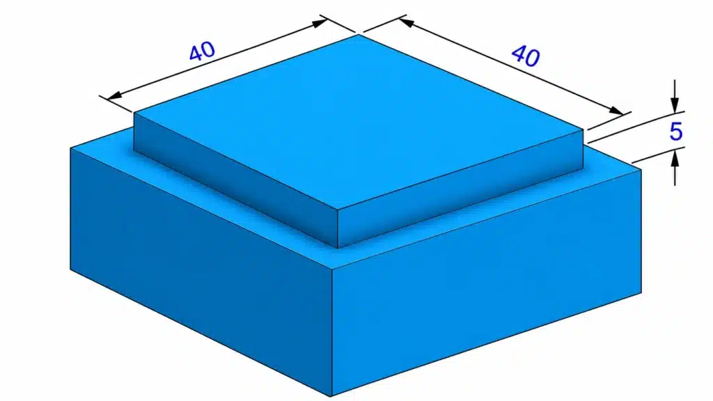
Set the G54 work origin at the center of the blank’s top face:
X0 Y0is the center of the 50 × 50 mm blank.Z0is the unmachined top surface.- The blank extends from
X-25toX25and fromY-25toY25. - The intended boss extends from
X-20toX20and fromY-20toY20. - The border’s finished level is
Z-5.
The exercise uses one 10 mm flat end mill, listed as Tool 1 with length offset H01. Surface finish is not the main objective; the purpose is to understand and check a complete programming sequence. The example assumes the cutter can reach the border without hitting clamps and that the stock and fixture match these dimensions. In a real job, read the actual drawing and setup sheet rather than relying on a verbal description.
Why the Origin Matters
The program’s numbers only describe the intended geometry if the physical G54 offset has been set to this exact origin. If G54 is set at a corner instead of the top center, X-25 Y-35 will place the tool somewhere else entirely. Tool length offset H01 likewise has to correspond to the measured Tool 1. For a fuller explanation of those references, see CASTMOLD’s CNC coordinate systems guide.
Step 2: Plan the Square Boss Milling Toolpath
Before typing code, mentally walk through the entire operation:
- Retract the Z axis to the machine reference position using the approved machine procedure.
- Select and change to the 10 mm end mill.
- Move to a starting XY position outside the blank while Z is clear.
- Start the spindle and coolant, and apply Tool 1’s length offset.
- Feed down outside the material to the cutting level,
Z-5. - Feed around the four sides of the boss at that level.
- Retract in Z, turn off coolant and spindle, and end the program.
The order matters. A good toolpath includes the approach and exit, not only the four cutting lines.
Calculate the Tool-Center Coordinates
The boss edge is at X±20 and Y±20. The cutter radius is 5 mm. Because the cutter is outside the material we want to keep, its center travels 5 mm beyond each boss edge. The four main tool-center lines are therefore X-25, Y25, X25, and Y-25.
Put another way, the 40 × 40 mm boss has a 50 × 50 mm tool-center rectangle for this external profile. This is a calculation for this 10 mm tool and this geometry, not a universal instruction to add 5 mm to every coordinate. A different cutter diameter changes the center path.
The program starts at X-25 Y-35, which places the cutter fully beyond the blank’s lower edge before the downward feed. It then moves up the left side, across the top, down the right side, and left along the bottom. The last move extends to X-35, beyond the blank, so the exit is outside the stock. This example puts the radius offset directly in the programmed coordinates; it does not activate G41 or G42 cutter radius compensation.
Tool-Center Path at a Glance
| Stage | Tool-center position or move | Purpose |
|---|---|---|
| Approach | X-25 Y-35 | Start outside the 50 mm blank |
| Feed to depth | Z-5 | Reach the border’s finished level outside the material |
| Left side | Y25 at X-25 | Remove the left 5 mm border |
| Top side | X25 at Y25 | Remove the top border |
| Right side | Y-25 at X25 | Remove the right border |
| Bottom and exit | X-35 at Y-25 | Remove the bottom border and run past the stock |
The cutter’s swept area, not just the centerline, determines what is removed. Check both against the stock and fixture in a toolpath simulation.
Step 3: Write the FANUC-Style G-Code Example
The program below stays close to the original exercise’s dimensions, coordinates, spindle setting, feeds, and path. It adds G21 for millimeters and G17 for the XY plane, and states G00 explicitly where the compensated tool moves to the clearance plane. Parenthesized text is a comment. The exact syntax and safe-return behavior must be checked on the intended control.
%
O0001 (40 MM SQUARE BOSS - TRAINING EXAMPLE)
(G54 X0 Y0 = STOCK TOP CENTER; Z0 = STOCK TOP)
(T01 = 10 MM FLAT END MILL; H01 = VERIFIED LENGTH OFFSET)

G91 G28 Z0.                 (RETURN Z TO MACHINE REFERENCE)
G21 G17 G94 G40 G49 G80    (MM, XY PLANE, FEED/MIN, CANCEL MODES)

T01 M06                     (SELECT AND CHANGE TO TOOL 1)
G00 G90 G54 X-25. Y-35.    (RESTORE ABSOLUTE MODE; START OUTSIDE BLANK)
S6000 M03                   (SPINDLE CLOCKWISE)
M08                         (COOLANT ON)
G00 G43 H01 Z50.           (APPLY LENGTH OFFSET; MOVE TO Z50)

G01 Z-5. F1500.            (FEED TO DEPTH OUTSIDE STOCK)
G01 Y25. F2500.            (LEFT SIDE)
G01 X25.                   (TOP SIDE)
G01 Y-25.                  (RIGHT SIDE)
G01 X-35.                  (BOTTOM SIDE AND EXIT)

G01 Z5. F1500.             (CONTROLLED INTERMEDIATE Z RETRACT)
G00 Z50.                   (RETRACT TO VERIFIED CLEARANCE)
M09                         (COOLANT OFF)
G49                         (CANCEL TOOL LENGTH COMPENSATION)
M05                         (SPINDLE STOP)
G91 G28 Z0.                 (RETURN Z TO MACHINE REFERENCE)
M30                         (END AND RESET)
%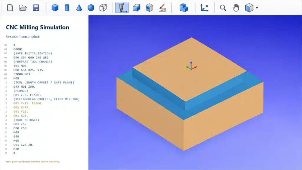
The values S6000, F1500, F2500, Z5, and Z50 come from the teaching example. They are not recommended settings for every aluminum alloy, end mill, machine, or fixture. Select cutting data from the actual tool and setup. In particular, Z5 is only an intermediate retract here; do not treat it as a clearance plane for moving over clamps. The operator must confirm that Z50 and the reference return clear the workholding and remain within machine travel.
Read the Program in Three Phases
Initialization and Tool Change
G91 G28 Z0. is a Z-only reference return in this FANUC-style example. Under G91, the programmed intermediate Z move is zero before the axis continues to the reference point. It is different from an absolute G90 G28 Z0., which can pass through the work-coordinate Z0 first. The Haas G28 description illustrates the distinction. Machine builders can implement home-return behavior differently, so verify the actual machine procedure.
G21 G17 G94 G40 G49 G80 establishes metric units and the XY plane, selects feed per minute, and cancels radius compensation, length compensation, and canned cycles. T01 M06 performs the tool change. The first positioning block after the tool change explicitly calls G90, even though absolute mode may already have been active. This matters because a tool-change macro or preceding operation may leave a different modal state. CASTMOLD’s G-code and M-code introduction covers these modes in more detail.
Approach and Cutting
G00 G90 G54 X-25. Y-35. selects the intended work offset and positions the tool outside the blank. S6000 M03 starts the spindle clockwise, while M08 turns coolant on. G00 G43 H01 Z50. activates the length offset and moves to a planned clearance position. Haas’s programming manual shows the same role for G43 Hnn and stresses matching the length-offset number to the selected tool.
The first G01 feeds to Z-5 while the cutter is outside the blank. The next four G01 blocks trace the border. F2500 remains modal after it is programmed, so the following X and Y cutting blocks use that feed until a new F value is issued. That is convenient, but it also means an omitted or inherited F value can matter. Review the active feed mode and each feed change.
Exit and Program End
After the bottom-side pass, the tool is at X-35 Y-25, outside the blank. The program feeds up to Z5, then rapids vertically to Z50. It turns off coolant, cancels the length offset, stops the spindle, returns Z to the reference point, and ends with M30. The exit is intentionally vertical before any other XY travel near the fixture.
Step 4: Check Your First CNC Program Line by Line
A program that looks readable is not yet ready for a first cut. The original exercise emphasizes a deliberate self-review; use a colleague’s review when a setup is new or costly. Verify the machine state, the code, and the physical setup together.
| Check | What to confirm in this example |
|---|---|
| Drawing and setup | Blank and boss dimensions, clamping, material, and Z-5 interpretation match the drawing |
| Units and plane | G21 selects mm and G17 selects XY; these are accepted by the control |
| Coordinate mode | G90 is restored on the first motion after the tool change |
| Work zero | G54 is actually set at the blank’s top center |
| Tool and length offset | Tool 1 is the 10 mm end mill and measured H01 matches it |
| Spindle and coolant | S6000 M03 and M08 match the tool and process plan |
| Feeds and depth | F1500, F2500, and Z-5 have been validated for the tool, engagement, material, and machine |
| Clearance | The approach, Z5, Z50, reference return, and clamps have all been checked in machine coordinates |
| End of program | The cutter leaves the stock, coolant and spindle stop, and M30 is present |
Simulate the code, confirm the toolpath envelope, then use the shop’s first-run procedure. Single-block execution, a reduced rapid override, and a suitable feed override help the operator observe the approach. Lowering feed override alone does not necessarily slow G00 rapid moves; Haas documents separate rapid override controls. Keep hands clear and use the machine’s normal guarding and emergency procedures. These checks matter more than any single example percentage.
Five Beginner Mistakes This Example Helps You Catch
1. Leaving Out a Feed Value
G01 uses a feed rate. If you assume the control will choose the right speed, it may instead alarm or use a modal value left from earlier code. State the first feed explicitly, then review every point where the intended feed changes.
2. Calling a Height “Safe” Without Checking the Fixture
Z5 is five millimeters above the stock top in this setup, but a clamp may stand higher. Z50 might clear it here, yet could be inappropriate on a different machine. Determine clearance from the actual part, workholding, tool length, and machine limits. Do not copy a Z number from another program and assume it is safe.
3. Using the Wrong Tool Length Offset
G43 H01 must refer to the length measured for Tool 1. A wrong H value can place the cutter at the wrong Z position even when all programmed coordinates are correct. Check how the specific controller handles length compensation at a tool change and at G49.
4. Rapid-Feeding Down Into Material
G00 is for positioning where the entire move is clear. In this example, the downward move to the cutting level is G01 and begins outside the stock. The later G00 Z50. happens only after a controlled Z retract. Rapid movement near the part should always be checked for possible collisions.
5. Omitting Decimal Points or Relying on Defaults
Some controls or settings interpret coordinates without decimal points differently from what a beginner expects. The exercise writes values such as X25. and Z50. explicitly. It also declares G21, G17, and G94 rather than relying on whatever was left active. Verify the target controller’s number format before importing any sample program.
Is Manual CNC Programming Still Worth Learning?
Yes, even when CAM generates most production code. Reading and writing a short manual program helps a CAM programmer debug an unexpected move, helps a setup technician understand what the machine will do next, and helps a production team adjust a simple operation without treating the code as a black box. Some straightforward jobs are still programmed or edited manually. The skill is most useful when paired with sound setup, simulation, and controller knowledge.
For a next exercise, rewrite the square-boss contour using G41 or G42 cutter radius compensation instead of calculating the 5 mm offset into every coordinate. That changes the required lead-in and lead-out, so simulate the compensated path and confirm the correct side before using it on a machine.
Final Takeaway
The process behind this first CNC milling program is simple: read the part, calculate the tool-center path, write the full approach-cut-exit sequence, and review it against the real setup. For this 50 mm blank and 10 mm end mill, the tool-center contour at X±25 and Y±25 leaves a 40 mm square boss after cutting the surrounding border to Z-5. The code becomes useful only when its offsets, cutting data, clearance, and controller behavior have been verified.
CASTMOLD applies CNC machining alongside die casting and mold manufacturing. If your part needs a reliable machining datum or a planned secondary operation, see our secondary CNC machining capability or contact the team with your drawing and project requirements.