G Codes and M Codes are the language that CNC machines understand.
In the previous article, we explained the five core systems of a CNC machine and how they work together. In this article, we are entering the world of CNC programming by learning the two main types of instructions used to control a machine tool.
This article uses the FANUC CNC code format as the main example.
- When I First Started Working in a Factory, the Program Made No Sense to Me
- What Are G Codes and M Codes?
- Essential G Codes and M Codes for CNC Beginners
- G90 and G91 — Absolute and Incremental Coordinates
- How Does G90 G28 Z0. Move?
- How Does G91 G28 Z0. Move?
- G54 to G59 — Work Coordinate System Selection
- M Codes Tell the Machine Which Function to Activate
- Common CNC M Codes
- Why Every CNC Program Needs a Safety Initialization Block
- Complete FANUC Program Example
- Summary: Understanding G Codes and M Codes
- CNC Machining Support from Cast Mold
- Aluminum Die Casting Services
When I First Started Working in a Factory, the Program Made No Sense to Me
I still remember when I first started working in a factory.
My instructor handed me a piece of paper covered with lines like these:
O0001
G94 G40 G49 G80
T01 M06
G90 G00 G54 X0. Y0.
S3000 M03
G43 H01 Z100.
G01 Z-5. F200
...
G00 Z50.
M09
G49
G91 G28 Z0.
M30
He said:
First, learn how to read this.
I stared at the program for a long time. I recognized a few letters, but almost everything else looked confusing.
Later, I discovered that these codes follow clear rules and are not as complicated as they first appear.
A CNC program mainly contains two types of instructions:
- Instructions that tell the cutting tool how to move
- Instructions that tell the machine which auxiliary function to activate
The first type is called G code.
The second type is called M code.
What Are G Codes and M Codes?
G Codes Tell the Cutting Tool How to Move
G codes are also known as preparatory function codes.
Their main function is to define how the cutting tool moves, including:
- Rapid positioning
- Linear cutting
- Circular interpolation
- Absolute coordinate movement
- Incremental coordinate movement
- Work coordinate system selection
- Machine reference return
A G code begins with the letter G, followed by two digits.
For example:
G00
G01
G54
G90
Before learning the individual commands, it is important to understand the difference between modal and non-modal G codes.
Modal G Codes
A modal code remains active after it has been programmed.
It continues to affect the following program blocks until another G code from the same group replaces it.
For example, after programming:
G01the CNC machine will continue using linear interpolation in the following blocks, even when G01 is not written again.
The mode remains active until another motion command, such as G00, G02, or G03, replaces it.
Non-Modal G Codes
A non-modal code is only effective in the program block where it appears.
It is executed once and does not remain active in later blocks.
For example:
G04is a dwell command. It only affects the current program block.
Essential G Codes and M Codes for CNC Beginners
The following commands are among the most important codes for anyone beginning to learn CNC programming. The explanations below follow the structure and examples provided in the original article.
G00 — Rapid Positioning
G00 moves the cutting tool to a specified position at the machine’s rapid traverse speed.
It is normally used for positioning rather than cutting.
Example:
G00 X100. Y50. Z200.This command rapidly moves the tool toward:
- X = 100 mm
- Y = 50 mm
- Z = 200 mm
Important Safety Warning
G00 does not necessarily move along one controlled straight-line path.
Multiple axes may move simultaneously at their maximum rapid speeds. Depending on the machine control and axis distances, the actual toolpath may be diagonal or dog-leg shaped.
For this reason, never use G00 carelessly when the cutting tool is close to the workpiece, fixture, clamps, or machine table.
When approaching the workpiece, use a controlled feed movement such as G01.
G01 — Linear Cutting
G01 moves the cutting tool along a straight line at a specified feed rate.
It is one of the most commonly used cutting commands in CNC machining.
Example:
G01 X50. Y50. F300.This command moves the tool in a straight line toward:
- X = 50 mm
- Y = 50 mm
The feed rate is:
F300The unit of the F value depends on the active feed mode.
Under G94
The feed rate is measured per minute:
mm/minUnder G95
The feed rate is measured per spindle revolution:
mm/revCNC milling machines commonly use G94.
G02 and G03 — Circular Interpolation
G02 and G03 are used to machine circular or arc-shaped toolpaths.
G02
Clockwise circular interpolation.
G03
Counterclockwise circular interpolation.
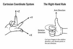
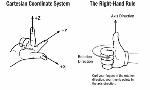
The direction is normally judged while looking from the positive direction of the selected axis toward the negative direction.
For an arc in the XY plane, this normally means looking from the positive Z-axis toward the workpiece.
Example using an R value:
G02 X50. Y0. R25. F200.This command moves the tool clockwise to:
- X = 50 mm
- Y = 0 mm
- Radius = 25 mm
- Feed rate = 200 mm/min
Example using center offsets:
G03 X0. Y50. I0. J25. F200.This command moves the tool counterclockwise using I and J to define the arc-center offset.
Easy Way to Remember
G02 = Clockwise
G03 = Counterclockwise
The direction should be viewed from the positive Z direction toward the negative Z direction when working in the XY plane.
G90 and G91 — Absolute and Incremental Coordinates
G90 and G91 are two commands that CNC beginners often confuse.
G90 — Absolute Coordinate Programming
Under G90, all programmed coordinates refer to the origin of the currently active coordinate system.
For example:
G90 G00 X50.This means:
Move to the absolute coordinate position X = 50 mm.
It does not mean moving another 50 mm from the current position.
A simple comparison is entering a specific destination into a navigation system.
G91 — Incremental Coordinate Programming
Under G91, every coordinate value represents a movement distance relative to the current tool position.
For example:
G91 G00 X50.This means:
Move another 50 mm in the positive X direction from the current position.
It does not mean moving to the absolute coordinate X = 50 mm.
A simple comparison is saying:
Move forward another 500 metres, and then turn right.
G90 and G91 Comparison
| Command | Coordinate Type | Meaning of X50 |
|---|---|---|
| G90 | Absolute coordinates | Move to X = 50 mm |
| G91 | Incremental coordinates | Move another 50 mm from the current position |
G28 — Return to the Machine Reference Point
G28 commands the machine axis to return to its preset reference point.
The basic format is:
G28 X_ Y_ Z_The X, Y, and Z values define an intermediate point.
Under G90, the intermediate point is interpreted as an absolute coordinate.
Under G91, the intermediate point is interpreted as an incremental movement.
This intermediate-point concept is the key to understanding why G91 G28 Z0. is commonly used instead of G90 G28 Z0..
What Is the Intermediate Point?
When the machine executes a G28 command, the axis does not simply move directly to the machine reference point in one step.
The movement normally contains two stages:
- Move to the programmed intermediate point
- Move from the intermediate point to the machine reference point
The programmed coordinate mode determines where that intermediate point is located.
How Does G90 G28 Z0. Move?
Assume the cutting tool is currently located at:
Z50.Now consider the following command:
G90 G28 Z0.Under G90, the value Z0. is an absolute coordinate in the currently active coordinate system.
Therefore, the movement happens in two stages:
- The Z-axis first moves from its current position to the absolute position
Z0. - It then moves from
Z0.to the machine reference point
Before executing a G28 return command, tool-length compensation is often cancelled.
In this situation, moving first to the work coordinate position Z0. may cause the tool to move downward toward the workpiece.
If the workpiece zero is located on the top surface of the part, the cutting tool may move directly into the workpiece.
That is why using:
G90 G28 Z0.without fully understanding the intermediate position can create a serious collision risk.
The original article emphasizes that the tool may first move toward the workpiece coordinate zero before returning to the machine reference position.
How Does G91 G28 Z0. Move?
Now consider:
G91 G28 Z0.Under G91, Z0. represents an incremental movement of zero.
In other words, the current tool position is used as the intermediate point.
The movement happens as follows:
- The Z-axis moves by an incremental distance of zero
- The current position becomes the intermediate point
- The Z-axis then returns to the preset machine reference point
Because the programmed intermediate movement is zero, the tool does not first move to the work-coordinate position Z0..
Instead, it begins returning from its current position toward the machine Z-axis reference point.
This is why CNC programs commonly use:
G91 G28 Z0.The meaning is:
Use the current Z position as the intermediate point, and then return the Z-axis to the machine reference point.
This movement logic is the main reason the original article recommends G91 G28 Z0. rather than G90 G28 Z0. for this situation.
G90 G28 and G91 G28 Comparison
| Command | Intermediate Point | Main Risk or Effect |
|---|---|---|
G90 G28 Z0. | Absolute Z0 in the active coordinate system | The tool may first move toward the workpiece zero |
G91 G28 Z0. | Zero incremental movement from the current position | The current position becomes the intermediate point before reference return |
Common FANUC Programming Format
G91 G28 Z0.Comment:
The Z-axis makes a zero incremental move and then returns to the machine Z reference point.G54 to G59 — Work Coordinate System Selection
G54 is one of the most commonly used work-coordinate-system commands.
After setting the workpiece origin during edge finding, probing, or tool setting, the coordinate values are entered into the G54 work offset.
When the program contains:
G54the machine interprets it as:
Use the workpiece origin stored in G54.
Additional work coordinate systems include:
G55
G56
G57
G58
G59
These represent the second through sixth standard work coordinate systems.
They are useful for:
- Machining multiple parts
- Using multiple fixtures
- Programming different workpiece positions
- Running several work offsets in one setup
M Codes Tell the Machine Which Function to Activate
M codes are also known as miscellaneous function codes or auxiliary function codes.
Unlike most G codes, M codes normally do not define the cutting tool’s position.
Instead, they control supporting machine functions such as:
- Starting and stopping the spindle
- Changing tools
- Turning coolant on and off
- Pausing the program
- Ending the program
- Calling a subprogram
The original article lists the following commonly used M codes.
Common CNC M Codes
| M Code | Function | Example or Explanation |
|---|---|---|
| M03 | Spindle forward rotation | Used with an S value, such as S3000 M03 |
| M04 | Spindle reverse rotation | Used for special tools or some tapping operations |
| M05 | Spindle stop | The spindle should normally stop before a tool change |
| M06 | Automatic tool change | Used with a T command, such as T02 M06 |
| M08 | Coolant on | Turns on coolant during cutting |
| M09 | Coolant off | Turns off coolant before tool changing or program completion |
| M00 | Program stop | Waits for the operator to press CYCLE START |
| M01 | Optional stop | Stops only when the OPTIONAL STOP switch is enabled |
| M30 | Program end and reset | Normally used at the end of a complete program |
| M98 | Subprogram call | Calls a specified subprogram, sometimes with a repeat count |
Why Every CNC Program Needs a Safety Initialization Block
There is one rule that CNC operators usually remember after witnessing even one serious machine collision:
Every CNC program should begin with a safety initialization block.
A common FANUC-format safety line is:
G90 G94 G40 G49 G80This line clears potentially dangerous modal conditions left active by a previous program.
G90 — Select Absolute Coordinate Mode
G90This prevents the new program from accidentally running under G91 incremental mode left active by the previous program.
Without G90, a coordinate intended as an absolute position might be interpreted as an additional movement distance.
G94 — Select Feed per Minute
G94This selects feed per minute, normally expressed in:
mm/minIt prevents the program from accidentally using G95 feed per revolution left active by another operation.
G40 — Cancel Cutter Radius Compensation
G40This cancels active cutter radius compensation.
It prevents a previous G41 or G42 compensation value from changing the programmed toolpath unexpectedly.
G49 — Cancel Tool-Length Compensation
G49This cancels active tool-length compensation.
It prevents a previous H offset from continuing to affect the Z-axis position in the new program.
G80 — Cancel Canned Cycles
G80This cancels active drilling, boring, tapping, or other canned cycles.
It prevents a drilling cycle left active by the previous program from being repeated unexpectedly in the new program.
The source article highlights these commands as essential for clearing retained modal conditions before the machining program begins.
Easy Safety Rule to Remember
G40 G49 G80 clear the previous compensation and cycles.
G90 G94 establish the correct coordinate and feed modes.
In simple words:
Clear the old settings first, and then establish the new program mode.
Why This Safety Block Matters
Imagine that the previous program ended while G43 tool-length compensation was still active.
The next program begins directly with G54, without first cancelling the remaining compensation.
When the Z-axis moves down, the control may still apply the previous tool-length offset. As a result, the tool may move tens of millimetres farther than expected and collide with the workpiece.
A short initialization block can prevent an expensive tool, workpiece, fixture, spindle, or machine accident.
Complete FANUC Program Example
Now let us combine the G Codes and M Codes into a simple program.
O0001
G94 G40 G49 G80
T01 M06
G90 G00 G54 X0. Y0.
S3000 M03
G43 H01 Z100.
G01 Z-5. F200
...
G00 Z50.
M09
G49
G91 G28 Z0.
M30
The program shown in the source uses tool change, work-offset selection, spindle control, tool-length compensation, cutting feed, coolant shutoff, compensation cancellation, and Z-axis reference return.
Line-by-Line Explanation
Program Number
O0001Defines the CNC program number.
Safety Initialization
G94 G40 G49 G80This line:
- Selects feed per minute
- Cancels cutter radius compensation
- Cancels tool-length compensation
- Cancels active canned cycles
For additional protection, many programs also include G90 in the safety initialization line:
G90 G94 G40 G49 G80Tool Change
T01 M06This selects Tool 1 and performs an automatic tool change.
Select Work Offset and Move to the Start Position
G90 G00 G54 X0. Y0.This line:
- Selects absolute coordinate programming
- Selects rapid positioning
- Activates the G54 work coordinate system
- Moves rapidly to X0 and Y0
Start the Spindle
S3000 M03This starts the spindle in the forward direction at:
3000 rpmActivate Tool-Length Compensation
G43 H01 Z100.This line:
- Activates positive tool-length compensation
- Uses tool-length offset H01
- Positions the Z-axis at 100 mm
Feed the Tool into the Workpiece
G01 Z-5. F200This moves the tool in a straight line to:
Z = -5 mmat a feed rate of:
200 mm/minRetract to a Safe Plane
G00 Z50.This rapidly retracts the tool to:
Z = 50 mmTurn Off Coolant
M09This turns off the coolant system.
Cancel Tool-Length Compensation
G49This cancels the active tool-length compensation.
Return the Z-Axis to the Reference Point
G91 G28 Z0.This uses incremental mode.
The Z-axis first performs a zero incremental move, meaning that its current location becomes the intermediate point. It then returns to the machine Z-axis reference point.
End the Program
M30This ends and resets the program.
Summary: Understanding G Codes and M Codes
G Codes and M Codes perform two different but complementary functions in a CNC program.
G Codes
G codes mainly control tool movement and coordinate modes.
Important examples include:
G00— Rapid positioningG01— Linear cuttingG02— Clockwise circular interpolationG03— Counterclockwise circular interpolationG90— Absolute coordinate programmingG91— Incremental coordinate programmingG28— Return to the machine reference pointG54— Select the first work coordinate system
M Codes
M codes mainly control auxiliary machine functions.
Important examples include:
M03— Start the spindleM05— Stop the spindleM06— Change the toolM08— Turn coolant onM09— Turn coolant offM30— End and reset the program
Key Points to Remember
- Modal codes remain active until another code from the same group replaces them.
- Non-modal codes only apply to the program block in which they appear.
G00should not be used carelessly near the workpiece.G90uses absolute coordinates.G91uses incremental coordinates.G28normally moves through an intermediate point before returning to the machine reference point.G90 G28 Z0.may first move the tool toward the absolute work-coordinate position Z0.G91 G28 Z0.uses the current position as the intermediate point before returning to the Z reference point.- Every program should begin with a safety initialization block such as
G90 G94 G40 G49 G80.
CNC Machining Support from Cast Mold
At Cast Mold, CNC machining is an important part of our one-stop manufacturing service.
We provide integrated support covering:
- Die-casting mold design
- Mold manufacturing
- Aluminum and zinc alloy die casting
- CNC machining
- Drilling and tapping
- Surface finishing
- Dimensional inspection
- Assembly and shipment
For die-cast components, CNC-machined features are often required for:
- Precision mounting holes
- Threads
- Sealing surfaces
- Bearing positions
- Assembly interfaces
- Flatness-critical areas
- Tight-tolerance dimensions
By combining tooling, die casting, CNC machining, surface treatment, and inspection, we help customers reduce communication time between multiple suppliers and improve dimensional consistency in batch production.
For a project evaluation, please provide:
- 2D drawings
- 3D models
- Material requirements
- Annual quantity
- Surface-finish requirements
- Critical tolerances
- Inspection requirements
Aluminum Die Casting Services
Learn more about our aluminum high pressure die casting services in China.