Before learning about coordinate systems, you may first read our guide on what a CNC machine is and how CNC technology developed.
A CNC machine coordinate system defines how the machine identifies the position of the cutting tool, workpiece and machining origin. Without correctly established coordinate references, a CNC machine cannot accurately convert programmed dimensions into actual axis movements.
A CNC machine cannot move accurately unless it knows three things:
- Where the machine is located within its travel range
- Where the workpiece is positioned on the machine table
- Where the cutting point of the selected tool is located
These positions are defined through coordinate references and compensation values.
For CNC operators, programmers and manufacturing engineers, understanding the machine coordinate system, work coordinate system and tool reference is essential. Incorrect axis directions, work offsets or tool compensation values can cause dimensional errors, tool collisions and damaged workpieces.
This article explains the right-hand rule, machine coordinate system, work coordinate system, G54–G59 work offsets and tool compensation. It also shows how these concepts are applied in die casting mold manufacturing and secondary CNC machining.
- What Is a CNC Machine Coordinate System?
- Why CNC Machines Need Coordinate Systems
- The Right-Hand Rule for CNC Machines
- How X, Y and Z Axes Are Defined
- What Is the Machine Coordinate System?
- What Is the Work Coordinate System?
- What Are G54 to G59 Work Offsets?
- Tool Reference Points and Tool Compensation
- Tool Length Compensation
- Tool Radius Compensation
- How the Coordinate References Work Together
- Why the Machine Table May Move in the Opposite Direction
- CNC Coordinate Systems in Die Casting Mold Manufacturing
- Machining Mold Cavities and Core Inserts
- Machining Slides and Insert Pockets
- CNC Machining of Die-Cast Parts
- Example: Aluminum Die-Cast Housing
- Why Coordinate Planning Should Begin During DFM
- Common CNC Coordinate Setting Errors
- Recommended Coordinate Verification Procedure
- CNC Coordinate Management at Cast Mold
- Aluminum Die Casting Services
What Is a CNC Machine Coordinate System?
A CNC machine coordinate system provides the positional reference required for accurate machine movement. It helps the CNC controller identify the machine position, workpiece origin and effective cutting point of the selected tool.
Why CNC Machines Need Coordinate Systems
A CNC machining program contains position commands.
For example, a program may instruct the machine to move to:
X50.000 Y25.000 Z-5.000However, these values are meaningless unless the CNC system knows where the X, Y and Z zero points are located.
The machine therefore needs several reference layers:
- A fixed reference for the machine itself
- A programmable reference for the workpiece
- Compensation values for the actual cutting tool
These references allow the same CNC program to be used even when:
- The workpiece is installed at a different position
- A fixture is moved
- A different cutting tool is loaded
- Several workpieces are installed on the same machine table
- Different machining operations use different datum points
Without correctly defined coordinate references, the CNC controller cannot convert programmed dimensions into actual machine movement.
The Right-Hand Rule for CNC Machines
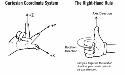
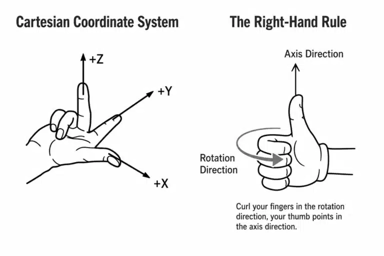
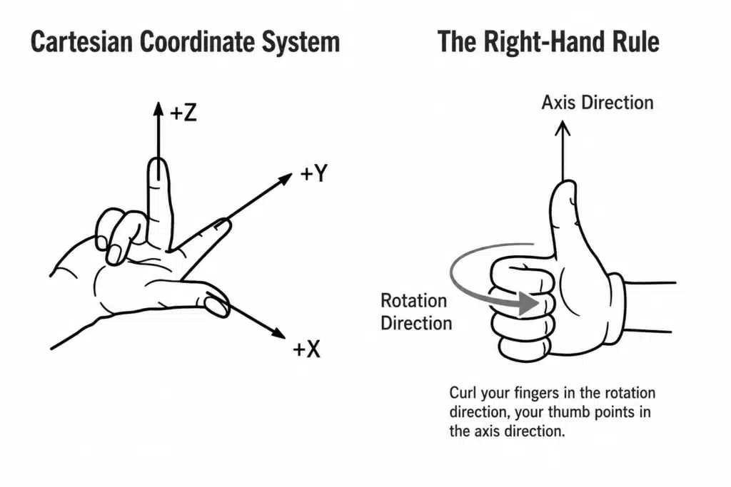
CNC machines normally use a right-handed Cartesian coordinate system.
The right-hand rule provides a standard method for identifying the positive directions of the X, Y and Z axes.
To visualize the rule:
- Point the right thumb in the positive X direction
- Point the right index finger in the positive Y direction
- Point the right middle finger in the positive Z direction
The three fingers should be perpendicular to one another.
This method helps programmers and operators understand the relationship between the three linear axes.
How X, Y and Z Axes Are Defined
Although CNC machines have different physical structures, their coordinate directions follow standardized principles.
Z Axis
The Z axis is normally parallel to the principal spindle axis.
The positive Z direction increases the distance between the cutting tool and the workpiece.
For a vertical machining center:
- The spindle is vertical
- Z+ normally moves the tool away from the workpiece
- Z− moves the tool toward the workpiece
A simple way to remember this is:
Positive Z means moving away from the workpiece.
This is one of the most important axis-direction rules in CNC machining.
X Axis
On a typical vertical machining center, when viewed from the operator’s position:
- X+ is usually toward the right
- X− is usually toward the left
The X axis is normally parallel to the main horizontal travel direction of the machine table.
Y Axis
The Y-axis direction is determined by the right-hand coordinate rule.
On a common vertical machining center:
- Y+ is normally away from the operator
- Y− is normally toward the operator
Typical Vertical Machining Center Directions
| Axis | Typical positive direction |
|---|---|
| X+ | Right |
| Y+ | Away from the operator |
| Z+ | Upward and away from the workpiece |
The exact physical movement may vary because some machines move the table while others move the spindle or column. CNC axis directions are defined according to the relative movement between the tool and the workpiece.
What Is the Machine Coordinate System?
The Machine Coordinate System, commonly abbreviated as MCS, is the basic coordinate reference of the CNC machine.
It is established by the machine tool manufacturer and is connected to the machine’s mechanical travel range.
The machine coordinate system is fixed. Operators and programmers normally do not change its zero position.
Machine Zero and Reference Position
Two related terms are often used:
- Machine zero
- Machine reference position
They are sometimes located at the same position, but technically they may not always be identical.
The reference position is a known physical position used by the control system to establish or confirm the machine’s axis locations.
Machines using incremental position feedback commonly require a return-to-reference procedure after power-up.
Modern machines equipped with absolute encoders may retain their axis positions after shutdown and may not require a traditional homing cycle every time the machine is started.
What Is the Machine Coordinate System Used For?
The machine coordinate system provides the foundation for:
- Axis travel limits
- Overtravel protection
- Tool-change positions
- Fixture clearance checks
- Work offset calculations
- Machine position display
- Safe machine movements
The mechanical or machine position shown on the CNC controller is normally based on the machine coordinate system.
Simple Comparison
The machine coordinate system can be compared to the global map of a city.
No matter where a building is located, its position can be defined according to the same city map.
In the same way, every workpiece, fixture and cutting tool is ultimately located within the machine coordinate system.
What Is the Work Coordinate System?
The Work Coordinate System, or WCS, is a coordinate reference established according to the workpiece drawing and machining datum.
Instead of programming every position relative to the machine’s fixed zero point, CNC programmers define a convenient zero point on the workpiece.
Common workpiece zero positions include:
- The center of the top surface
- A corner of the raw material
- The center of a bore
- The center of a circular part
- A machined locating hole
- A fixture reference point
The selected origin should match the design datum, machining strategy and inspection method whenever possible.
Why Is a Work Coordinate System Necessary?
The component drawing may define a hole as being 50 mm from the left edge and 30 mm from the bottom edge.
The CNC program can therefore use the drawing datum as its origin.
However, the physical position of that origin inside the CNC machine depends on:
- Where the workpiece is clamped
- How the fixture is installed
- Which machine table position is used
- Whether the part has been reinstalled
- Whether several parts are being machined together
The operator measures the actual workpiece origin and stores its position as a work offset.
The CNC system then converts the programmed workpiece coordinates into machine coordinates.
What Are G54 to G59 Work Offsets?
On many CNC control systems, including commonly used FANUC systems, G54 to G59 are standard work coordinate offsets.
Each code represents an independent work coordinate system.
| Work offset | Typical application |
|---|---|
| G54 | First workpiece or first machining datum |
| G55 | Second workpiece or second datum |
| G56 | Third workpiece or third datum |
| G57 | Additional fixture or operation |
| G58 | Additional fixture or operation |
| G59 | Additional fixture or operation |
A line such as:
G54tells the CNC controller that the following programmed coordinates should be interpreted relative to the G54 workpiece origin.
Example: One Workpiece
When only one component is installed on the table, the program may use G54 for the complete machining operation.
Example: Multiple Workpieces
Suppose three identical aluminum housings are installed on one fixture.
The operator may define:
- G54 for workpiece 1
- G55 for workpiece 2
- G56 for workpiece 3
The same machining subprogram can then be repeated using the three different work offsets.
Example: Multiple Machining Operations
A component may require different datums during different operations.
For example:
- G54 for top-surface machining
- G55 for side machining
- G56 for a locating-hole datum
Using separate offsets helps organize the setup and reduces unnecessary coordinate calculations inside the CNC program.
Extended Work Offsets
Some CNC systems support extended work offsets, such as:
G54.1 P1
G54.1 P2
G54.1 P3
The number of available extended offsets depends on the machine controller and installed options.
These additional offsets are useful for:
- Multi-part fixtures
- Pallet systems
- Automated production lines
- Tombstone fixtures
- Flexible manufacturing systems
Tool Reference Points and Tool Compensation
Different cutting tools have different lengths and diameters.
For example:
- A face mill may be relatively short
- A deep-hole drill may be much longer
- A ball-end mill has a different cutting geometry
- A reamer may have a smaller diameter than the programmed hole path
The CNC system must know the exact relationship between the spindle reference position and the tool’s effective cutting point.
This relationship is managed through tool offsets and compensation.
Tool Length Compensation
Tool length compensation allows the CNC system to account for differences in tool length.
A typical command is:
G43 H01In this command:
- G43 activates positive tool length compensation
- H01 calls the length offset stored in register 01
The actual implementation and sign convention may vary depending on the machine, controller, measurement method and company programming standard.
Why Tool Length Compensation Matters
Without tool length compensation, every tool change would require the entire CNC program to be rewritten according to the new tool length.
With correct tool length offsets, different tools can machine the same workpiece datum without changing the programmed Z coordinates.
Tool length compensation is particularly important for:
- Drilling
- Tapping
- Deep-pocket machining
- Mold cavity machining
- Multi-tool machining operations
- Automatic tool changing
Tool Radius Compensation
Tool radius compensation allows the CNC controller to offset the tool center from the programmed component contour.
Common commands include:
G41
G42
G40
Typically:
- G41 applies cutter compensation to one side of the programmed path
- G42 applies compensation to the opposite side
- G40 cancels cutter compensation
The exact left or right relationship must be determined according to the tool movement direction.
Why Tool Radius Compensation Is Useful
Tool radius compensation makes it easier to:
- Adjust component dimensions
- Compensate for tool wear
- Use a slightly different tool diameter
- Separate component geometry from tool-center calculations
- Optimize finishing dimensions without rewriting the complete contour
However, the lead-in, lead-out and compensation direction must be programmed correctly. Improper use can cause alarms, gouging or incorrect component dimensions.
How the Coordinate References Work Together
The CNC controller combines several pieces of information to determine the required machine position.
Conceptually, the process is:
Programmed position
+ work offset
+ tool compensation
= actual machine movement
This formula is a simplified explanation rather than a universal controller calculation formula.
The complete relationship may also include:
- Local coordinate shifts
- Fixture offsets
- Rotary-axis transformations
- Five-axis kinematic transformations
- Tool center point control
- Dynamic work offsets
- Machine calibration parameters
For standard three-axis machining, the main relationship can be understood as follows:
Layer 1: Machine Coordinate System
This is the fixed physical reference of the machine.
Layer 2: Work Coordinate System
G54, G55 or another offset defines where the workpiece origin is located inside the machine coordinate system.
Layer 3: Tool Compensation
Tool length and radius offsets define where the actual cutting point is located relative to the spindle and programmed path.
The CNC system combines these references to position the cutting edge correctly on the workpiece.
Why the Machine Table May Move in the Opposite Direction
One common source of confusion is that the physical movement of the machine table may appear opposite to the axis direction shown on the controller.
For example, on some vertical machining centers:
- The operator presses X+
- The table physically moves left
- The tool therefore moves right relative to the workpiece
The CNC coordinate direction is based on the relative movement of the tool with respect to the workpiece, not only on which machine component physically moves.
This is why two different machines may appear to move differently even though they follow the same programming coordinate convention.
Safe Operating Practice
When operating an unfamiliar machine:
- Use a low feed rate
- Select a small jog increment
- Observe the relative movement between tool and workpiece
- Confirm the axis direction before rapid movement
- Check clearance before starting automatic operation
This simple procedure can prevent collisions and setup errors.
CNC Coordinate Systems in Die Casting Mold Manufacturing
Coordinate control is especially important when manufacturing die casting molds.
A die casting mold contains many components that must align accurately, including:
- Cavity inserts
- Core inserts
- Slides
- Lifters
- Ejector pin holes
- Cooling channels
- Runner systems
- Overflow pockets
- Venting slots
- Insert pockets
- Parting surfaces
The work coordinate system must match the selected machining and assembly datums.
Machining Mold Cavities and Core Inserts
For cavity and core machining, the workpiece origin is often established using:
- The center of the mold insert
- A precision reference corner
- Ground datum surfaces
- Locating holes
- The center of the mold base
The datum should remain consistent across operations whenever possible.
A stable coordinate strategy improves the relationship between:
- Rough machining
- Heat treatment
- Semi-finishing
- Finishing
- EDM electrode positioning
- Wire-cutting operations
- Mold assembly
- Final inspection
Poor datum planning can cause cavity mismatch, incorrect insert positioning or dimensional deviation after multiple setups.
Machining Slides and Insert Pockets
Slides and movable mold components frequently involve angled surfaces and several coordinate references.
The engineer must consider:
- Slide movement direction
- Locking surface angle
- Shut-off surface position
- Insert assembly datum
- Machining accessibility
- Fixture orientation
- Repeated setup accuracy
When a component must be machined in several orientations, separate work offsets may be used for each setup.
For example:
- G54 for the main cavity surface
- G55 for a side shut-off surface
- G56 for an angled slide feature
This allows the program structure to remain clear and reduces manual coordinate conversion.
CNC Machining of Die-Cast Parts
Die-cast components often require secondary CNC machining after casting.
Common machined features include:
- Sealing surfaces
- Threaded holes
- Bearing bores
- Connector holes
- Mounting datums
- Precision assembly surfaces
- Flat installation surfaces
- Positioning holes
For repeat production, the work coordinate system should be established from stable casting or fixture datums.
The datum design must account for:
- Casting dimensional variation
- Parting-line flash
- Draft angles
- Ejector marks
- Clamping deformation
- Porosity in machined areas
- Fixture repeatability
- Machining allowance
Example: Aluminum Die-Cast Housing
Consider an aluminum die-cast housing that requires:
- Milling of a sealing surface
- Drilling of four mounting holes
- Tapping of two threaded holes
- Boring of a precision connector opening
A practical coordinate strategy may use:
- Z zero on the finished sealing surface
- X and Y zero at the center of the main locating feature
- A fixture designed around stable casting datums
- Tool length offsets for each cutting tool
- Tool radius or wear compensation for critical dimensions
This arrangement makes the program easier to verify and allows dimensions to be adjusted without changing the complete toolpath.
Why Coordinate Planning Should Begin During DFM
Coordinate planning should not begin only after the casting or mold insert reaches the CNC machine.
It should be reviewed during the DFM and process-planning stage.
The engineering team should consider:
- Which surfaces will be used as machining datums
- Which features will be used for fixture positioning
- Whether the datum will remain stable after casting
- Whether the cutting tool can reach each feature
- Whether machining will expose internal porosity
- How the component will be measured
- Whether multiple operations use consistent references
- How deformation will affect the finished dimensions
Early coordinate and datum planning can reduce:
- Fixture complexity
- Setup time
- Dimensional variation
- Rework
- Scrap
- Inspection difficulty
- Production cost
Common CNC Coordinate Setting Errors
1. Incorrect Work Offset
If the wrong G54, G55 or other work offset is selected, the machine may move to the wrong workpiece position.
2. Incorrect Z-Zero Setting
An incorrect Z reference can result in:
- Cutting too deeply
- Machining above the component
- Tool breakage
- Fixture collision
3. Wrong Tool Length Offset
Calling the wrong H value may position the tool at an incorrect height.
4. Incorrect Tool Radius Compensation
An incorrect D value or G41/G42 direction can produce an oversized or undersized profile.
5. Workpiece Installed in the Wrong Orientation
The work offset may be correct, but the component may be rotated or reversed in the fixture.
6. Inconsistent Programming and Setup Datums
If the CAM programmer and machine operator use different zero-point assumptions, the program cannot run correctly.
7. Ignoring Table and Tool Relative Movement
Misunderstanding physical table movement may cause the operator to jog the machine in the wrong direction.
Recommended Coordinate Verification Procedure
Before starting automatic machining:
- Confirm the selected program and work offset
- Verify the workpiece orientation
- Check the X, Y and Z datum positions
- Confirm tool numbers and offset registers
- Review the G43, H and D values
- Check fixture and tool clearance
- Use single-block operation for the first run
- Reduce rapid override
- Perform an air-cut or safe-height test when necessary
- Inspect the first finished component before batch production
For molds and high-value components, these checks are especially important because a single coordinate error can damage both the workpiece and the cutting tool.
CNC Coordinate Management at Cast Mold
At Cast Mold, coordinate and datum planning is considered throughout the manufacturing process.
Our workflow can include:
- Drawing and 3D model review
- DFM analysis
- Moldflow analysis
- Die casting mold design
- CNC and EDM process planning
- Mold manufacturing
- Mold trial and sampling
- Aluminum or zinc die casting
- Secondary CNC machining
- Surface finishing and inspection
By aligning the design datum, mold datum, machining datum and inspection datum, we can reduce unnecessary coordinate conversions and improve production consistency.
Aluminum Die Casting Services
Learn more about our aluminum high pressure die casting services in China.