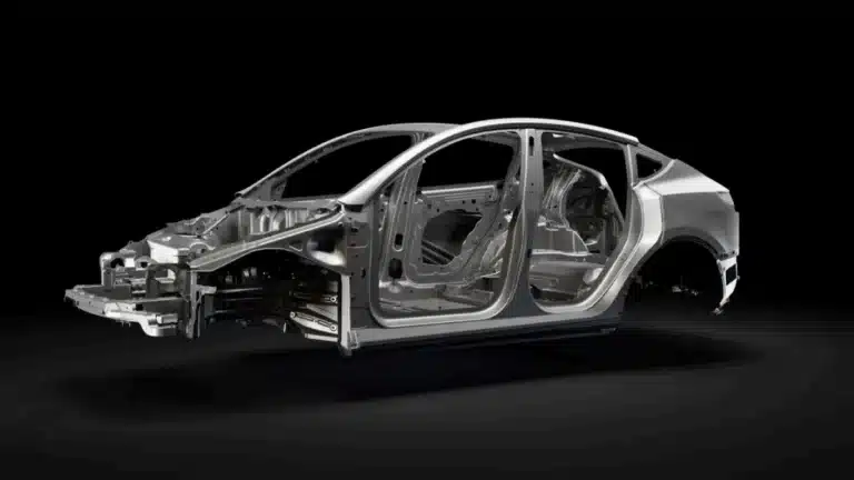
Lightweighting has pushed automakers to replace welded steel assemblies with large, thin-wall aluminum die castings. Automotive doors, battery trays, rear underbodies and similar structural parts now combine complex geometry, long flow lengths and tight mechanical requirements.
However, when wall thickness drops to 2–3 mm and the casting spans more than a meter, high pressure die casting (HPDC) becomes much more sensitive to shot profiles, thermal control and intensification pressure. Porosity, cold shuts and shrinkage cavities can quickly become show-stoppers.
This article summarizes a research case on high pressure die casting simulation of a complex thin-wall aluminum automotive door, focusing on:
- How to model filling and solidification for such a large casting
- How different slow-shot profiles affect air entrapment and temperature distribution
- How intensification pressure influences shrinkage porosity
- How simulation results matched 6800-ton production trials
The practical takeaways are directly applicable to engineers working on large structural HPDC parts.
- 1. Case Overview: Thin-Wall Automotive Door Casting
- 2. Multi-Physics High Pressure Die Casting Simulation Model
- 3. Comparing Three Slow-Shot Profiles in the Shot Sleeve
- 4. Effect of Intensification Pressure on Shrinkage Porosity
- 5. Validation on a 6800-Ton HPDC Machine
- 6. Practical Takeaways for HPDC Engineers
- 7. From Design to Delivery: How Cast Mold Applies HPDC Simulation
- Aluminum Die Casting Services
1. Case Overview: Thin-Wall Automotive Door Casting
The study uses an aluminum automotive door inner panel as the reference part:
- Material: AlSi10MnMg aluminum alloy
- Casting size: approx. 1135 × 665 × 60 mm
- Main wall thickness: around 2.5 mm, with local areas up to 4 mm
- Net weight: about 5.56 kg

| Material | Density (g/cm³) | Liquidus Temperature (°C) | Solidus Temperature (°C) |
|---|---|---|---|
| AlSi10MnMg | 2.5 | 594 | 540 |
| H13 | 7.367 | 1458 | 1375 |
The die is made from H13 hot-work tool steel. Thermal properties for both alloy and steel were obtained via Thermo-Calc to feed into the simulation.
Gating and overflow system
Because the door is essentially a large, irregular thin-wall shell:
- The ingate is located near the center of the casting, to keep flow lengths balanced.
- A “star-shaped” ring gate distributes molten metal radially, helping the flow front reach distant corners at similar times.
- Gate thickness is matched to the local wall thickness at the gate area to avoid jetting and to keep filling stable.
- Overflow and venting channels are placed at the outer edges and corners to evacuate air and catch dross.

Thermal control in the die
To stabilize die temperature and reduce thermal fatigue, the die incorporates:
- Conventional cooling water channels
- Vacuum temperature control in critical areas
- Local thermal control around the oil cylinder seat

The goal is to keep the cavity in a dynamic thermal equilibrium: hot enough for complete filling and good surface quality, but cool enough to maintain cycle time and die life.
2. Multi-Physics High Pressure Die Casting Simulation Model
To understand both air entrapment during filling and shrinkage defects during solidification, the research team used a multi-physics model on a cloud-based HPDC CAE platform.
Key elements of the high pressure die casting simulation:
- Flow field (filling stage)
- A Lattice Boltzmann Method (LBM) is used to describe molten metal flow in the shot sleeve and gating system.
- A VOF (Volume of Fluid) model tracks the interface between liquid metal and air, making it possible to predict where gas may be trapped in the sleeve or cavity.
- Temperature and solidification
- An energy equation with latent heat models cooling and solidification in both casting and die.
- A Stefan-type formulation describes the movement of the solid–liquid interface.
- A solid fraction model links temperature to local solid/liquid fraction.
- 4D metal/die interfacial heat transfer
- A “4D” interfacial heat transfer model captures how the heat transfer coefficient between metal and die evolves with:
- time after metal impingement and
- location on the die surface.
- The coefficient is dynamically updated every time step to reproduce real contact conditions more accurately than a constant value.
- A “4D” interfacial heat transfer model captures how the heat transfer coefficient between metal and die evolves with:
- Mesh and process conditions
- Minimum cavity element size: about 0.65 mm; total mesh cells ~190 million, capturing thin walls and local hot spots.
- Melt temperature: 660 °C
- Die preheat: 200 °C
- Ambient temperature: 20 °C

With this framework, the team could virtually test different slow-shot profiles and intensification pressures before committing to expensive trials.
3. Comparing Three Slow-Shot Profiles in the Shot Sleeve
The first question was: How does the slow-shot profile in the shot sleeve affect air entrapment and temperature uniformity?
Three slow-shot strategies were evaluated; all switch to a high-speed phase of 4.6 m/s near the cavity:
- Scheme A: constant slow speed 0.2 m/s → 4.6 m/s
- Scheme B: constant slow speed 0.5 m/s → 4.6 m/s
- Scheme C: uniform acceleration from 0 to 1.23 m/s, then 4.6 m/s (critical slow speed determined by simulation)
3.1 Flow behavior in the shot sleeve
Simulation of metal flow in the shot sleeve reveals:
- Scheme A (0.2 m/s)
- The metal moves with a wavy, rolling front, causing strong air entrapment.
- Long residence time in the sleeve leads to excessive cooling and higher risk of oxide films forming at the surface.
- Scheme B (0.5 m/s)
- Higher speed reduces residence time, but the metal still shows irregular wave motion, again mixing air and oxides into the melt.
- Scheme C (0–1.23 m/s, uniform acceleration)
- The metal front remains smooth and forward-leaning.
- No significant back-flow or rolling waves are observed, drastically reducing the risk of air entrapment in the sleeve.

In short: too slow (A) and too abrupt (B) both promote gas entrapment; a controlled uniform acceleration (C) keeps the front stable.
3.2 Filling time distribution in the cavity
All three profiles share a similar high-speed filling time (~0.04 s), but the low-speed phase and total filling time differ:
- Scheme A: slow fill ≈ 4.14 s, total ≈ 4.18 s
- Scheme B: slow fill ≈ 2.00 s, total ≈ 2.04 s
- Scheme C: slow fill ≈ 2.94 s, total ≈ 2.99 s

More important than total time is the gradient of filling time across the casting:
- Schemes A and B show large local differences in filling time between regions near and far from the gate. That can cause temperature imbalance, cold shuts and visible flow marks.
- Scheme C keeps the filling time gradient relatively small across the door, giving a more uniform thermal history.
3.3 Temperature distribution during filling
The temperature field at the end of filling is critical for thin-wall aluminum:
- Scheme A
- Temperature at the gate is reasonably uniform.
- But from shot sleeve to ingate, temperature drops quickly, reducing fluidity.
- At the end of filling, some upper regions show sharp temperature gradients and relatively low temperatures → risk of cold shuts and flow marks.
- Scheme B
- The temperature field is non-uniform. For example, a gate in the lower right region cools much faster.
- After filling, the casting is almost uniformly around 640 °C, meaning the part is too hot overall, which can extend solidification time and increase shrinkage risk.
- Scheme C
- Gate areas display uniform filling temperature, and the temperature drop from shot sleeve to gate is moderate.
- Metal fluidity is good, and the overall temperature distribution at the end of filling is more balanced.


Conclusion:
Among the three slow-shot profiles, the uniform acceleration strategy (Scheme C) offers the best compromise:
- Smooth front in the shot sleeve (minimal air entrapment)
- Reasonable total filling time
- Relatively uniform temperature distribution in the thin-wall cavity
4. Effect of Intensification Pressure on Shrinkage Porosity
After selecting Scheme C as the best shot profile, the study then explored how intensification pressure affects shrinkage and micro-shrinkage.
Four intensification levels were simulated for Scheme C:
- 40 MPa, 60 MPa, 80 MPa, 90 MPa
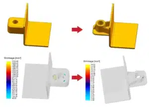
4.1 Shrinkage distribution at different pressures
Simulation of solidification and porosity prediction shows
- 40 MPa:
- Shrinkage cavities (shrinkage + micro-shrinkage) concentrate around the gate region and near hot spots.
- The total defect volume is relatively large.
- 60 MPa:
- Porosity becomes mainly confined to the upper and lower sides of the door.
- 80 MPa:
- Only three localized shrinkage zones remain: one near the gate and one at each of the upper and lower hot spots.
- 90 MPa:
- Shrinkage defects in the evaluated regions are essentially eliminated; the casting is predicted to be free of significant shrinkage porosity.

(a)40MPa, (b)60MPa, (c)80MPa, (d)90MPa

The study tracks three critical locations (A, B, C) and measures shrinkage volume vs. pressure. For example, at point A, shrinkage volume decreases from around 199 mm³ at 40 MPa to 0 mm³ at 90 MPa.
4.2 Key lesson
For large thin-wall automotive castings:
- Moderate intensification (40–60 MPa) may not be sufficient to fully compensate solidification shrinkage in remote hot spots.
- Raising intensification pressure toward 80–90 MPa, within the limits of die strength and machine capacity, can significantly reduce or eliminate shrinkage porosity in critical regions.
5. Validation on a 6800-Ton HPDC Machine
To verify the high pressure die casting simulation results, the researchers conducted production trials on a 6800-ton HPDC machine:
- Shot profile: Scheme C
- Uniform acceleration from 0 to 1.23 m/s (critical slow speed)
- High-speed shot at 4.6 m/s
- High-speed start position 900 mm
- Intensification pressure: 90 MPa
After removing gating and overflow systems, the door casting weighed approximately 5.56 kg. The castings showed:
- Clear and accurate surface contours
- No visible cracks, flash or cold shuts
- X-ray inspection of critical zones revealed no obvious gas porosity or shrinkage cavities, agreeing with the simulation predictions.


This alignment between virtual and real results confirms that the HPDC simulation approach is reliable for process window development and defect prediction in such large thin-wall parts.
6. Practical Takeaways for HPDC Engineers
For engineers working on structural automotive aluminum parts, this case provides several practical guidelines:
- Treat the shot sleeve as part of the casting system
- Poorly controlled slow-shot phases (too slow or too fast) cause rolling waves that trap air and oxides before the metal even reaches the gate.
- Design slow-shot profiles with smooth acceleration, tailored to the alloy and shot sleeve geometry.
- Optimize filling time gradients, not just total time
- Large local differences in filling time across a big casting lead to uneven temperature, cold shuts and internal stress.
- Aim for a balanced filling sequence where distant ends don’t lag far behind gate-adjacent regions.
- Focus on temperature uniformity at the end of filling
- Excessive cooling risks cold shuts; too much residual heat raises shrinkage risk.
- Use simulation to tune melt temperature, die preheat, cooling circuits and shot speed.
- Don’t underestimate intensification pressure
- For large thin-wall parts with long flow paths, higher intensification pressures (≈80–90 MPa) can be necessary to eliminate shrinkage defects, as long as die and machine limits are respected.
- Validate simulation with targeted trials
- After simulation narrows down candidates, use limited shop trials and X-ray/testing to confirm the optimized process window before ramping to full production.
7. From Design to Delivery: How Cast Mold Applies HPDC Simulation
At Cast Mold, we work with exactly these kinds of challenges every day:
- Complex aluminum and zinc alloy HPDC parts for automotive, telecom, lighting and industrial equipment
- Thin-wall geometries, long flow lengths and tight cosmetic/mechanical specs
- Projects that demand porosity control, structural integrity and stable mass production
Based on cases like the automotive door example above, our engineering team:
- Uses CAE-driven flow and solidification analysis to design gating, venting and overflow systems
- Optimizes slow-shot profiles and intensification pressures before cutting steel
- Validates critical parts with DFM reviews, simulation reports and X-ray / CMM inspections
- Helps customers move smoothly from prototype to ramp-up, reducing risk and iteration time
If your next project involves a large or thin-wall aluminum part and you’re worried about porosity, cold shuts, or inconsistent quality, high pressure die casting simulation is no longer optional—it’s one of the most effective tools to secure a stable, repeatable process from design to delivery.
Aluminum Die Casting Services
Learn more about our aluminum high pressure die casting services in China.


")
