When we talk about die casting part design, we are not only deciding how a part looks. We are also fixing its porosity risk, distortion behaviour, cycle time, scrap rate, machining cost and assembly efficiency before the first tool is even cut.
Good die casting part design = good DFM (Design for Manufacturing) + good DFA (Design for Assembly):
- DFM focuses on stable casting, easy filling & solidification, reasonable tooling, and predictable quality.
- DFA focuses on how this casting is assembled with other components: positioning, tolerances, accessibility, fasteners and functional integration.
Below are 14 practical structural principles for die casting part design, distilled and reorganized from shop-floor experience and DFM/DFA best practices for aluminum and zinc die castings.
- 1. Wall Thickness of Die Casting Parts
- 2. Minimum Hole Size and Depth
- 3. Avoid Excessively Thin Die Sections
- 4. Rib Design
- 5. Draft Angles
- 6. Fillet and Corner Design
- 7. Boss (Support Post) Design
- 8. Lettering and Logos
- 9. Thread Design
- 10. Facilitate Trimming of Flash and Gates
- 11. Tolerance Requirements for Die Castings
- 12. Simplify Die Structure and Reduce Tooling Cost
- 13. Machining on Die Castings
- 14. Use Die Castings to Simplify Product Structure and Reduce Cost
- Aluminum Die Casting Services
1. Wall Thickness of Die Casting Parts
(1) Choose a reasonable wall thickness
If the wall is too thin, the melt is difficult to fill, causing short shots, cold shuts, or incomplete features.
If the wall is too thick, solidification is slow and the grains are coarse, which increases the risk of:
- Internal defects: shrinkage porosity, gas porosity, segregation
- Surface defects: sinks and depressions
- Lower mechanical properties and higher weight and cost
As a general guideline for HPDC:
- The maximum wall thickness of most die castings should not exceed ~5 mm.
- Thin-wall sections (within process capability) help improve density, strength, and pressure resistance.
- Locally thick regions should be cored out so that the overall wall thickness becomes more uniform and the part weight is reduced.
| Wall Area (cm²) | Al & Mg Alloys – Minimum Wall Thickness (mm) | Al & Mg Alloys – Recommended Wall Thickness (mm) | Zn Alloys – Minimum Wall Thickness (mm) | Zn Alloys – Recommended Wall Thickness (mm) |
|---|---|---|---|---|
| ≤ 25 | 0.8 | 2.0 | 0.5 | 1.5 |
| 25 ~ 100 | 1.2 | 2.5 | 1.0 | 1.8 |
| 100 ~ 500 | 1.8 | 3.0 | 1.5 | 2.2 |
| > 500 | 2.5 | 3.5 | 2.0 | 2.5 |
When a local region must be thicker for functional reasons, use pockets or hollow sections to reduce mass and keep the solidification pattern uniform.

(2) Maintain uniform wall thickness and smooth transitions
Whenever possible, the cross-section of the die casting should have uniform wall thickness or only gradual changes. If differences are unavoidable (because of function or assembly), the ratio of thick to thin sections should generally not exceed 3:1.
Design tips:
- Use drafted or tapered transitions to avoid abrupt jumps in thickness.
- Avoid “step” sections where the metal flow suddenly slows or accelerates.
- Remember that sections with different thicknesses solidify at different times, which can create large internal stresses and lead to cracking and distortion.
Well-designed transitions help:
- Stabilize melt flow and improve filling
- Reduce turbulence and surface folding
- Minimize internal stress and deformation risks

2. Minimum Hole Size and Depth
Very small or very deep holes are difficult to fill and vent in HPDC, and they also weaken the die.
In general:
- For aluminum and magnesium alloys, the minimum practical hole diameter is around 2.0–2.5 mm.
- For zinc alloys, due to better fluidity, the minimum practical hole diameter can be about 1.0–1.5 mm.
- Economical hole depth is typically around 4–6 times the diameter (4d–6d), and the technical limit can be about 8–12d, depending on alloy and whether the hole is blind or through.
If a hole must be smaller or deeper than these guidelines:
- Consider casting a shallow recess / pilot mark and completing the feature by drilling or reaming.
- At the same time, check hole-to-hole, hole-to-edge, and hole-to-slot distances to ensure the die steel has enough strength to withstand thermal and mechanical loads.
3. Avoid Excessively Thin Die Sections
The structural design of the part directly affects the thinnest sections of the die cavity:
- If the die steel in some areas is too thin, its strength drops sharply.
- Under repeated high-temperature cycling and injection pressure, such thin areas are prone to deformation, bending, cracking, or breakage.
From a DFM perspective, part geometry should avoid forcing the die to have thin slivers of steel or extremely narrow ribs in the cavity.

4. Rib Design
Ribs in a die casting serve two main purposes:
- Increase stiffness and strength of the part and reduce deformation (instead of simply thickening the walls).
- Guide the metal flow to improve filling and reduce defects.

(1) Rib dimensions
A common design reference (T = nominal wall thickness):
- Rib base thicknesst:
- Typically 0.6–1.0 × T, and generally not larger than the local wall thickness.
- Rib heightH:
- Usually H ≤ 5 × T.
- Fillet radius at the rib baseR:
- Typically t ≤ R ≤ 1.25t, and often close to the local wall thickness.
- Draft angle on ribs:
- Around 1–3° to facilitate ejection.
(2) Avoid large flat plates
Large, flat surfaces without ribs are easy to warp, dent, or vibrate in service. Adding properly oriented ribs:
- Increases stiffness
- Stabilizes filling
- Reduces local sinks and deformation
(3) Match rib direction to metal flow
Where possible, orient ribs in the direction of fill:
- Helps the melt flow more steadily
- Reduces dead zones and turbulence
- Improves air evacuation
(4) Arrange ribs symmetrically and evenly
- Aim for a balanced and symmetric rib layout to distribute stiffness and shrinkage more evenly.
- Avoid rib intersections that create very thick nodes, which are prone to shrinkage porosity and sinks.
5. Draft Angles
Different alloys have different tendencies to stick to the die, so the recommended draft angles vary:
- Aluminum alloys: highest adhesion; inner surfaces typically need ~1° draft.
- Magnesium alloys: slightly less adhesion; inner surfaces about 0.75°.
- Zinc alloys: lowest adhesion; inner surfaces around 0.5°.
For outer surfaces, the draft angle is usually twice the internal draft to ensure the casting stays on the moving (core) side during ejection.
Remember:
- Local texturing, EDM, or roughness may require additional draft.
- Complex features (deep ribs, bosses) often benefit from larger draft to reduce sticking and die wear.
6. Fillet and Corner Design
(1) Avoid external sharp corners
External sharp corners cause multiple issues:
- Thin metal at the edge → poor filling and weak structure
- Stress concentration → higher crack risk
- Safety issues during handling
Use external radii wherever possible.
(2) Use internal fillets; avoid internal sharp corners
Internal fillets at wall intersections are critical for both part quality and die life:
- Improve metal flow, reduce turbulence, and help air escape
- Greatly reduce stress concentration and cracking risk
- Reduce thermal stress in the die, improving die life
General rule:
- Internal fillet radius ≈ local wall thickness
- External radius = internal radius + wall thickness

Fillets that are too small behave like sharp corners; fillets that are too large locally thicken the part and may cause shrinkage porosity and surface sinks.
(3) Benefits for plating and finishing
For die castings that require electroplating or other coatings, fillets help achieve:
- More uniform current distribution
- More uniform coating thickness
- Less risk of burning or thin spots on corners

7. Boss (Support Post) Design
Bosses are common in HPDC parts for mounting, fastening, and supporting structures. Good boss design should respect uniform wall thickness and die steel strength.
Key points:
- Avoid bosses too close to walls or to each other
- If bosses are too close, wall sections in the die or the casting become very thin or very thick, which is harmful to both quality and die life.

- Limit boss height
- Very tall bosses are hard to fill and mechanically weak. Consider reducing height or supporting them with ribs.
- Add ribs around bosses
- Use circumferential or radial ribs to increase strength and assist filling.
- Avoid “isolated” bosses with no structural support.

- Optimize inclined bosses
- For inclined bosses, re-designing the geometry can often avoid complex side core mechanisms and simplify the die, lowering tooling cost.

8. Lettering and Logos
(1) Raised lettering is preferred
For part numbers, logos, and symbols:
- Design them as raised features on the casting (recessed in the die).
- This keeps die machining and maintenance costs lower compared with engraving recessed letters in the casting.
(2) Recommended lettering dimensions
To ensure good filling and readability:
- Minimum stroke width W: ≥ 0.25 mm
- Letter height H: 0.25–0.5 mm
- Draft angle θ: ≥ 10°

Additionally:
- Avoid lettering on side walls that would require side cores or create undercuts.
- Place text on surfaces aligned with primary draw direction to simplify the die.
9. Thread Design
Threads are sensitive features in HPDC.
- For external threads, avoid full-length threaded sections. Provide unthreaded lead-in and run-out zones where possible.
- For internal threads, do not cast them directly in most cases. Because of filling, venting, and die cleaning issues, it is generally better to:
- Cast a core hole with proper DFM design
- Finish the thread by tapping or thread-forming, or
- Use threaded inserts where appropriate
This approach improves both dimensional accuracy and service performance of threaded joints.
10. Facilitate Trimming of Flash and Gates
Flash and gate removal is a significant part of die casting production cost. Good part design can make this operation faster and more reliable.
Key guidelines:
- Avoid sharp angles between walls and the parting line
- Sharp angles at the parting line make trimming difficult and increase the risk of cosmetic damage.

- Simplify part geometry near the parting line
- Complex shapes that cause deeply recessed or jagged flash areas will require more manual work.
- Where possible, make the parting line simple and smooth.

- Avoid overly strict cosmetic requirements at gate areas
- If the design demands a fully invisible gate and flash removal area, additional machining or polishing may be required, raising cost.
- Where function allows, relax cosmetic requirements around gates to reduce processing steps.
11. Tolerance Requirements for Die Castings
(1) Understand the cost of tight tolerances
Very tight part tolerances directly imply very tight die tolerances, which bring several side effects:
- Higher die manufacturing cost
- Shorter die life due to high stress and wear
- More frequent die maintenance and replacement
- Increased inspection frequency and more die components
- Higher scrap rate for castings
Therefore, from a DFM standpoint:
Set the casting tolerances as loose as possible, provided that functional and assembly requirements are still fully satisfied.
(2) Reduce machining by using functional tolerances
By relaxing where possible:
- Many dimensions can be held “as cast”, eliminating machining.
- This reduces cost and preserves the dense surface layer of the casting.
(3) Use the parting line to control critical dimensions
Strategic parting line selection can improve tolerance control:
- If concentricity of D1 and D2 is critical → choose a parting line that keeps them in the same die half.
- If D1 and D3 must be concentric → adjust the parting line accordingly.
- If the consistency of D1 at one end is important → position the parting line so that the critical surface stays in a single cavity half.

The goal is to minimize relative movement between critical features by keeping them on the same side of the die.
12. Simplify Die Structure and Reduce Tooling Cost
From a DFM perspective, a good die casting part is one that does not force a complicated die.
(1) Avoid internal undercuts
Internal undercuts can only be formed by side cores or secondary machining, which:
- Increase die complexity and cost
- Increase cycle time and maintenance requirements
Where possible, redesign the part to:
- Replace internal undercuts with open features aligned to the main draw direction
- Consolidate features to avoid multiple side actions

(2) Avoid external undercuts
For external surfaces:
- Redesign protrusions, hooks, or recesses that create external undercuts so they can be pulled in the main opening direction.
- Consider replacing undercut geometry with snap-fit alternatives in the assembly or with separate components if needed.

(3) Ensure side core motion is unobstructed
Where side cores are unavoidable, check that:
- No ribs, bosses, or fillets block core motion.
- The cores can move fully in and out without interference.
Sometimes a minor change in part geometry (e.g., moving a rib or changing a fillet) can allow much simpler and more reliable side core mechanisms.

(4) Avoid fillets along the parting line
Fillets on the parting line:
- Complicate the die machining
- Reduce local die steel strength
- Make sealing and flash control more difficult
Where possible, keep the parting line sharp and clean, and place fillets away from it.
(5) Choose a simple parting line
When comparing candidate parting lines:
- Prefer the one that yields the simplest die structure, with fewer side cores and easier machining.
- A simpler die is generally more robust, cheaper, and easier to maintain.
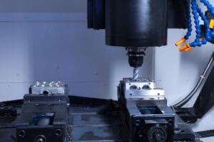
13. Machining on Die Castings
(1) Avoid machining whenever possible
Die castings can already achieve relatively high levels of dimensional accuracy and surface quality. Machining should be avoided when:
- Functional tolerances can be met in the as-cast condition.
- Cosmetic requirements can be satisfied by as-cast surfaces or simple finishing.
Reasons:
- The surface of a die casting is a dense, high-strength skin layer. Machining removes this layer and exposes a more porous interior.
- Local porosity may be exposed during machining, leading to leaks or cosmetic defects.
- Every extra machining operation adds cost and lead time.
(2) Design for easy machining with minimal stock
When machining is truly necessary:
- Design the part so that machining surfaces are easily accessible with standard tools.
- Avoid deep pockets or awkward tool approaches.
- Keep machining allowances as small as practical to protect the dense skin and reduce cycle time.

Typical allowances (one side), depending on size:
1. Surface Machining Allowance
| Max. Size of Machined Surface (mm) | ≤ 50 | 50–120 | 120–260 | 260–400 | 400–630 |
|---|---|---|---|---|---|
| Single-Side Machining Allowance (mm) | 0.3–0.5 | 0.4–0.7 | 0.6–1.0 | 0.8–1.4 | 1.2–1.8 |
2. Hole Machining Allowance
| Hole Diameter (mm) | ≤ 6 | 6–10 | 10–18 | 18–30 | 30–50 | 50–80 |
|---|---|---|---|---|---|---|
| Machining Allowance (mm) | 0.05 | 0.10 | 0.15 | 0.20 | 0.25 | 0.30 |
- Flat surfaces: roughly 0.3–1.8 mm as size increases from small (~50 mm) to large (~600+ mm).
- Hole diameters: roughly 0.05–0.30 mm stock depending on diameter.
The exact values should be chosen based on process capability and quality requirements.
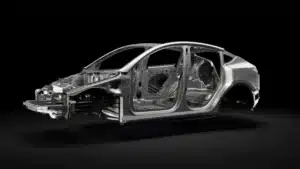
14. Use Die Castings to Simplify Product Structure and Reduce Cost
Finally, die casting design is not only about making a “castable” part; it is also an opportunity to optimize the whole product from a DFA standpoint.
(1) Replace machined parts with die castings
When loads, precision, and operating conditions permit:
- A complex machined steel or aluminum component may be replaced with a single die casting, drastically reducing:
- Material waste
- Machining time
- Component handling and assembly steps

(2) Reduce part count using multifunctional die castings
Die cast parts can provide complex 3D geometry and integrated functions, such as:
- Built-in ribs, bosses, clips, and fastening features
- Integrated housings instead of separate plates and brackets
- EMI shielding for electronic products by replacing plastic housings with conductive die cast shells

By smartly combining functions, you can:
- Reduce the number of components
- Simplify assembly and logistics
- Lower overall system cost while improving robustness

From Design to Delivery – How Cast Mold Supports Your Die Casting Projects
At Cast Mold, we treat die casting part design as the starting point of quality, not an afterthought. Based in Dongguan and Shenzhen, our team combines in-house mold making, high pressure die casting (HPDC), CNC machining and surface finishing under an ISO 9001 & IATF 16949 quality system to keep every project traceable and stable from design to mass production.
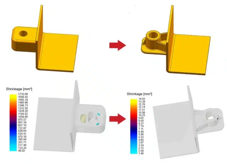
For new projects, we typically start with a DFM review and, when needed, Moldflow simulation to evaluate wall thickness uniformity, gating and venting layout, core strength, and risk of porosity or distortion. This allows us to optimize part and mold structure together – reducing trial loops, shortening lead time and protecting tool life.
Once the design is confirmed, our toolroom and HPDC shop work as one system: precision machining of the die, controlled shot parameters, and CMM inspection of critical dimensions ensure that what you model is what you receive. Whether you need rapid sampling, small-batch validation, or stable mass production, our goal is simple: precision from design to delivery.
If you are developing a new aluminum or zinc die cast part and want to check whether the structure is truly manufacturable, you are welcome to share your 3D models and 2D drawings with us. We can provide a practical DFM suggestion + quotation package, and help you turn a good concept into a reliable die casting solution.
Aluminum Die Casting Services
Learn more about our aluminum high pressure die casting services in China.


")